 |
|||
|
|
|||
|
Page Title:
Removal of Hydraulic Head Assembly. |
|
||
| ||||||||||
|
|
 TM 9-2910-226-34
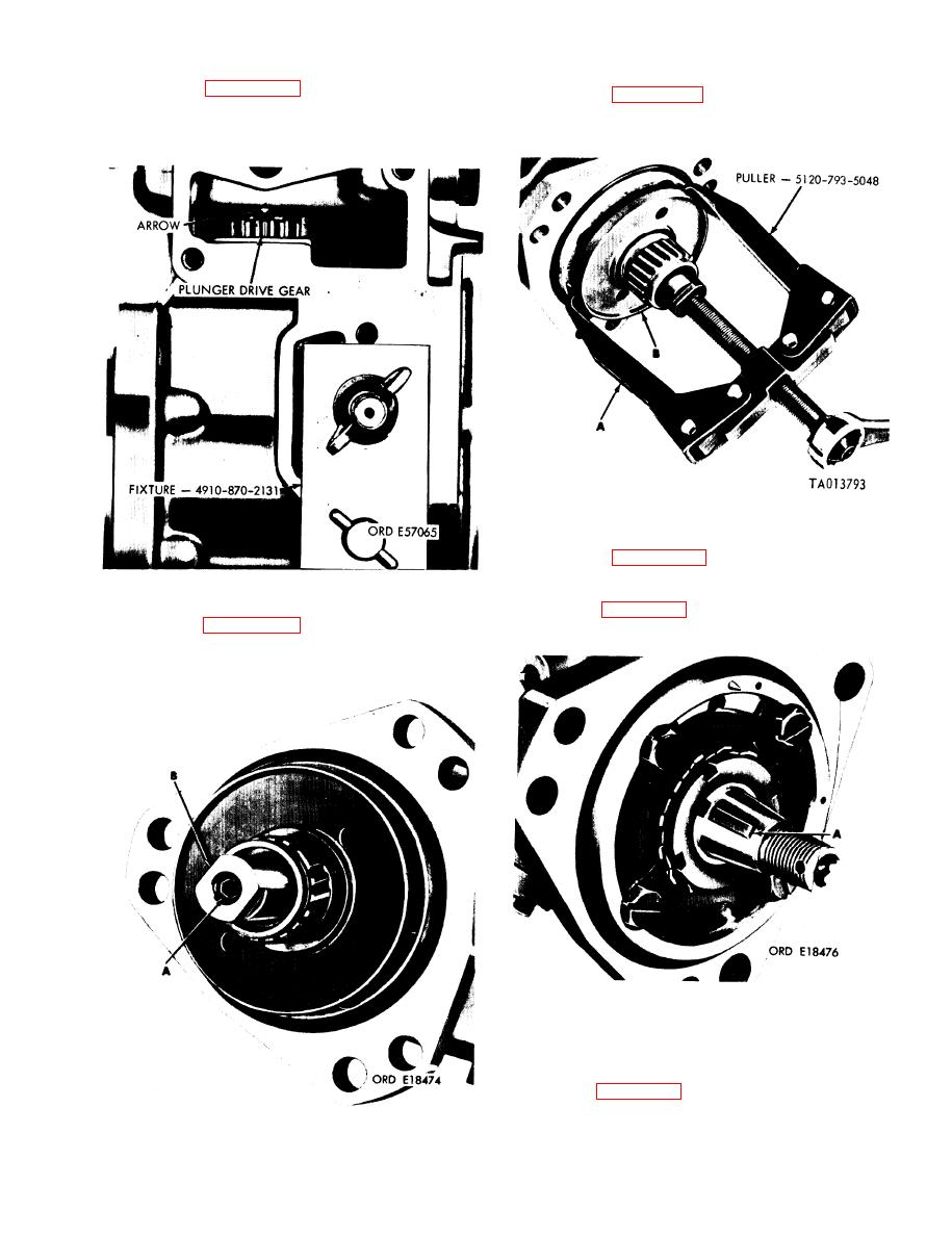
slotted tooth of plunger drive gear alines with arrow
loosen timing device hub (B).
on injection pump housing. Lock camshaft in this
position using camshaft fixture.
Figure 3-18. Removing timing device hub using puller
5120-793-5048.
setscrew (A), camshaft nut (B) and timing device
hub .
Figure 3-16. Locking camshaft using fixture4910-870-2131.
setscrew (A) and camshaft nut (B) two or three
turns.
Figure 3-19. Removing or installing pump Woodruff key.
3-13. Removal of Hydraulic Head Assembly.
NOTE
Sub-Paragraph a below applies only to code
F and G injection pumps.
Remove and discard filter screw copper gasket (B)
and remove oil filter (C). Or remove screw (D),
Figure 3-17. Loosening camshaft nut.
3-7
|
|
Privacy Statement - Press Release - Copyright Information. - Contact Us |
