 |
|||
|
|
|||
|
Page Title:
Section II. DESCRIPTION AND DATA |
|
||
| ||||||||||
|
|
 TM 9-2910-226-34
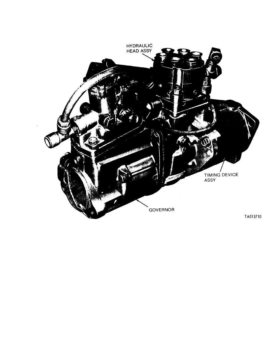
Figure 1-12. Metering and distributing fuel injection pump assembly (code A), right rear view.
improvements. Your letter or DA Form 2028
1-2. Maintenance Forms and Records. Maintenance
forms and records that you are required to use are
(Recommended Changes to Publications and Blank
explained in TM 38-750.
Forms) should be mailed direct to Commander,
US Armv Tank-Automotive Command, ATTN:
1-3. Recommendation for Maintenance Publications
AMSTA-M, Warren, MI 48090. A reply will be
Improvements. You can help to improve this manual
furnished direct to you.
by calling attention to errors and by recommending
Section Il. DESCRIPTION AND DATA
C.
As viewed from the governor end, the side on
1-4. Localization of Fuel Injection Pump Com-
the viewer's right will be the right side.
ponents. a. In this manual, the terms defined in b
and c below will be used to describe the location of
1-5. General. a. The metering and distributing fuel
the fuel injection pump components.
infection pump assembly is a constant-stroke,
b. The timing device end of the pump will be
sleeve control type. T h e
distributing-plunger,
called the front and the governor end the rear.
plunger is actuated by a camshaft and tappet
1-13
|
|
Privacy Statement - Press Release - Copyright Information. - Contact Us |
