 |
|||
|
|
|||
|
Page Title:
DETERMINE LONGEST BLADE OF LOW PRESSURE POWER TURBINE ROTOR |
|
||
| ||||||||||
|
|
 TM 9-2835-255-34
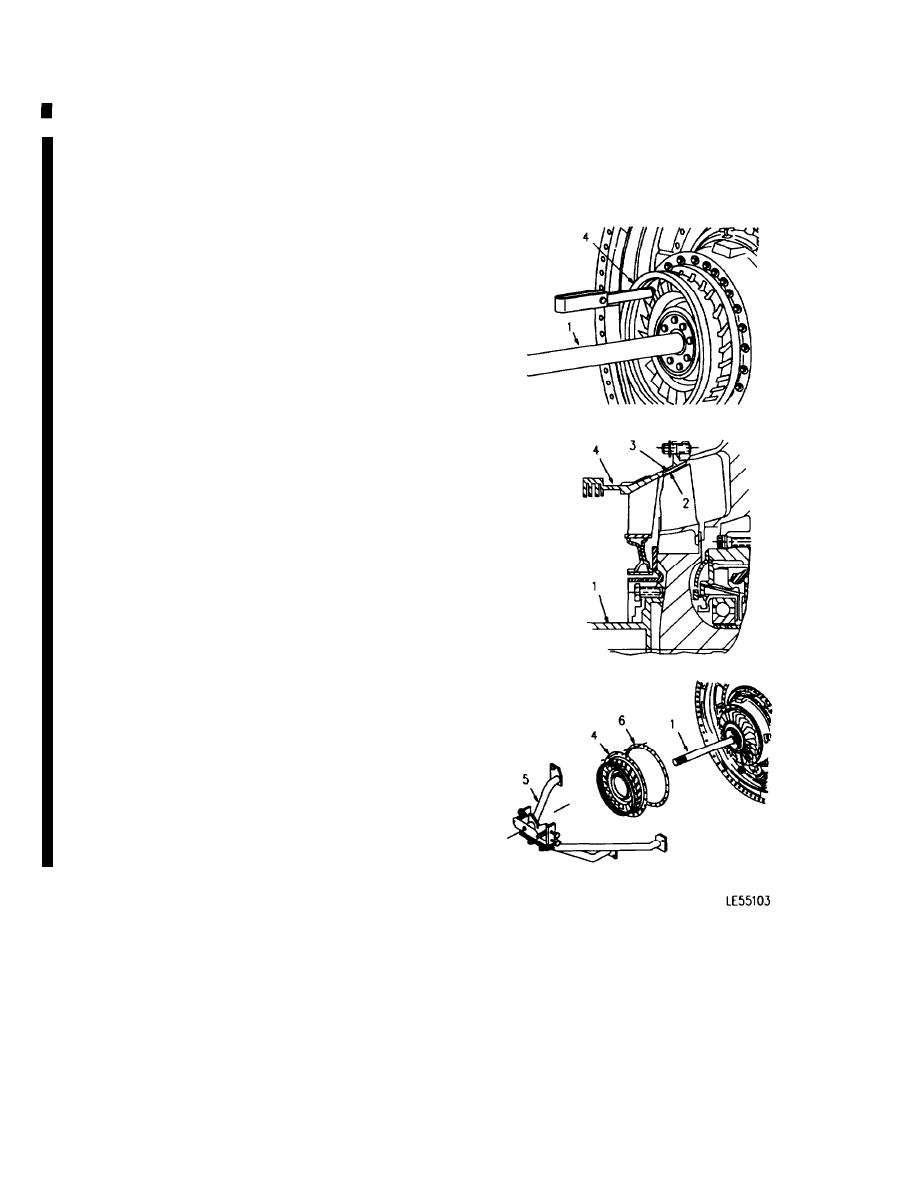
LOW PRESSURE TURBINE NOZZLE REPLACEMENT (Sheet 9 of 11)
10. DETERMINE LONGEST BLADE OF LOW PRES-
SURE POWER TURBINE ROTOR (1).
a.
Insert a 0.015 inch (0.381 mm) minimum feeler
gage between top of power turbine rotor
blades (2) and cylinder area (3) of turbine
nozzle (4).
b.
Slowly rotate power turbine rotor shaft (1) to
determine longest rotor blade.
11. CHECK LOW PRESSURE POWER TURBINE
ROTOR BLADE TIP CLEARANCE.
a.
Measure power turbine rotor blade tip clear-
ance by inserting feeler gage on top of longest
rotor blade and rotating power turbine rotor
shaft (1) one complete revolution (360 de-
grees).
b.
Tip clearance gap shall be maintained be-
tween 0.018-0.020 inch (0.457-0.508
mm).
c.
If tip clearance is within limits specified in step
b., go to step 12.
NOTE
Thicker spacer ring will increase tip clear-
ance. Thinner spacer ring will decrease
tip clearance.
d.
If tip clearance is not within limits specified in
step b., remove G.P. runout fixture (5), LP tur-
bine nozzle (4), and spacer ring (6). Replace
spacer ring (6) as necessary to obtain re-
quired tip clearance. Then repeat INSTALLA-
TION steps 1. through 11.
12. REMOVE G.P. RUNOUT FIXTURE (5).
Go on to Sheet 10
6-100
Change 6
|
|
Privacy Statement - Press Release - Copyright Information. - Contact Us |
