 |
|||
|
|
|||
|
Page Title:
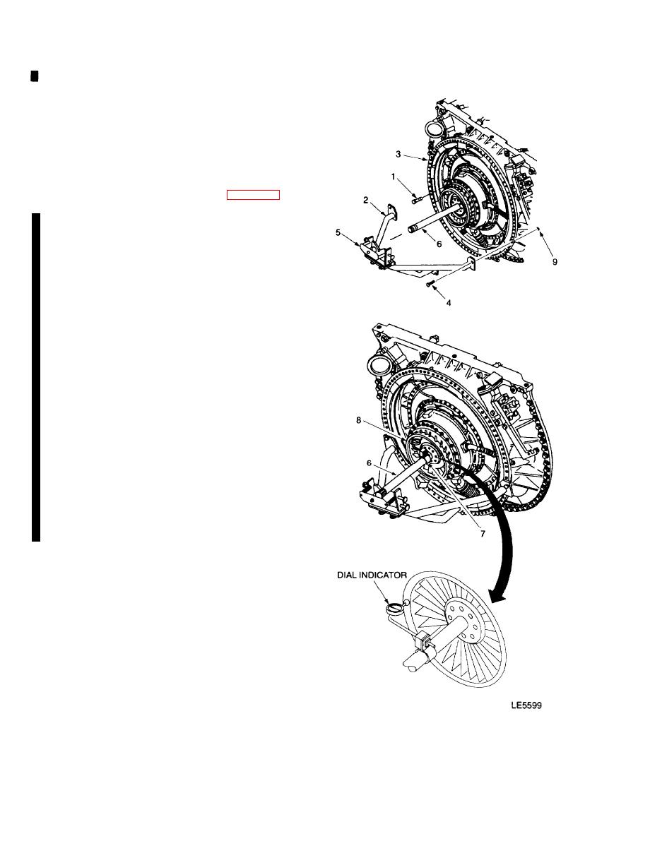
INSTALL DIAL INDICATOR ASSEMBLY |
|
||
| ||||||||||
|
|
 TM 9-2835-255-34
LOW PRESSURE TURBINE NOZZLE REPLACEMENT (Sheet 5 of 11)
Insure low pressure turbine nozzle is fully
c.
seated by attempting to insert a 0.002 inch
feeler gage at 3, 6, 9 and 12 o'clock positions
at low pressure turbine nozzle to power tur-
bine housing mating surface. If 0.002 inch
feeler can be inserted remove low pressure
turbine nozzle, inspect for minor nicks or burrs
if necessary. Repeat step 2 on page 6-95.
d. Apply antiseize compound to 6 nozzle flange
bolts (1). Evenly space and install bolts (1) in a
crisscross pattern and tighten between
70-95 lb-in (8-11 Nm) torque.
3. INSTALL G.P. RUNOUTS FIXTURE, (2) TO BOLT
FLANGE (3) USING 4 BOLTS (4) AND NUTS (9).
4. INSTALL DIAL INDICATOR ASSEMBLY (7) ON
POWER TURBINE SHAFT (6).
Install and loosely secure dial indicator as-
a.
sembly (7) on power turbine shaft (6) with
screw clamp.
Slide dial indicator assembly (7) rearward to
b.
12 o'clock position and allow indicator gauge
plunger to contact low pressure turbine nozzle
flange (8) and recess slightly in indicator
housing.
Tighten dial indicator assembly screw clamp.
c.
5. PULL BACK ON TOGGLE PAD (5) AND PLACE
PLUG OVER FORWARD END OF POWER TURBINE
SHAFT (6).
Go on to Sheet 6
6-96
Change 6
|
|
Privacy Statement - Press Release - Copyright Information. - Contact Us |
