 |
|||
|
|
|||
|
|
|||
| ||||||||||
|
|
 TM 9-2835-255-34
LOW PRESSURE TURBINE NOZZLE REPLACEMENT (Sheet 4 of 11)
NOTE
If any of these conditions exist, reas-
semble power turbine assembly with
original hardware and replace rear engine
subassembly (page 628).
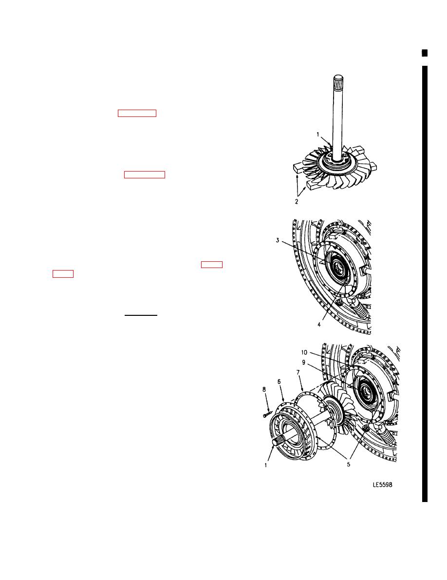
5. PLACE LP TURBINE ROTOR AND SHAFT (1)
NOSE UP ON TWO WOOD BLOCKS (2) IN A CLEAN
AND SECURE LOCATION.
6. INSPECT NO. 5 SEAL AND DIAPHRAGM (3) FOR
DAMAGE (REFER TO PAGE 646 FOR REMOVAL
INSTRUCTIONS). REPLACE AS REQUIRED.
7. INSPECT INSIDE OF PT HOUSING (4) FOR
FOREIGN OBJECTS OR DAMAGE. REMOVE ANY
FOREIGN OBJECTS. REPAIR MINOR BURRS,
NICKS OR SCRATCHES AS NECESSARY IF SE-
VERE FOREIGN OBJECT DAMAGE OR CRACKING
OF HOUSING IS PRESENT, REASSEMBLE POWER
TURBINE ASSEMBLY WTH ORIGINAL HARDWARE
AND SALVAGE GAS TURBINE POWER UNIT (PAGE
INSTALLATION:
CAUTION
Use care during and after installation of
turbine rotor shaft (1) to avoid damaging
No. 5 bearing air and oil seals.
1. USING MARKER, PLACE AN ALIGNMENT MARK
(5) ON NEW OR REPLACEMENT NOZZLE (6) AT
SAME LOCATION AS MARK MADE ON REMOVED
NOZZLE.
2. INSTALL TURBINE ROTOR SHAFT (1), SPACER
RING (7), TURBINE NOZZLE (6) AND 6 BOLTS (8).
TIGHTEN BOLTS (8) BETWEEN 705 LB-IN (81
NM) TORQUE.
a.
Have assistant hold shaft (1) and carefully seat
in No. 5 bearing (9).
b.
Install spacer ring (7) and nozzle (6) on PT
housing (10). Align locating matchmarks (5)
on nozzle (6) and PT housing (10), and align
bolt holes.
Go on to Sheet 5
6-95
Change 6
|
|
Privacy Statement - Press Release - Copyright Information. - Contact Us |
