 |
|||
|
|
|||
|
|
|||
| ||||||||||
|
|
 TM 9-2835-255-34
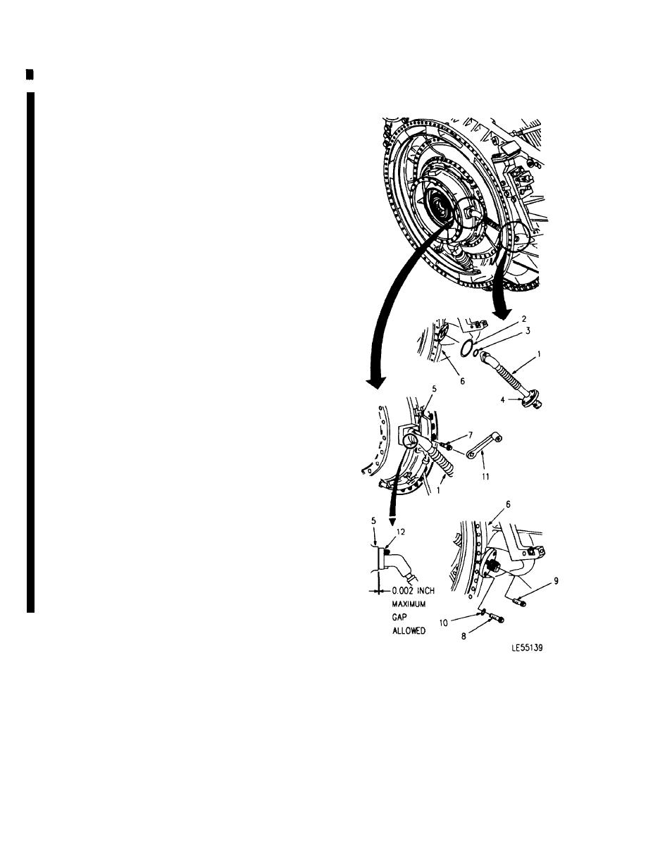
GAS TURBINE POWER UNIT REPLACEMENT (Sheet 27 of 30)
26. INSTALL COOLING TUBE ASSEMBLY (1), PACK-
ING MATERIAL (2) AND PREFORMED PACKING (3).
a.
Lightly coat packing material (2) with Ultra-
them assembly fluid and install onto outer
flange (4) of cooling tube (1).
b.
Install preformed packing (3) onto gas turbine
power unit housing (5).
c.
Insert cooling tube (1) through regenerator (6)
and onto gas turbine power unit housing (5).
d. Apply antiseize compound to two bolts (7).
Install bolts (7) but do not torque.
e.
Apply antiseize compound to three (long)
bolts (8) and one (short) bolt (9). Loosely
install bolts (8) with washers (10), and bolt (9).
NOTE
Torque two inner bolts (7) first, then torque
outer bolts (8, 9).
27. USING TORQUE ADAPTER (11), TIGHTEN
BOLTS (7) BETWEEN 49-57 LB-IN (5.5-6.5 NM)
TORQUE. WAIT 10 MINUTES AND RETORQUE.
28. TIGHTEN BOLTS (8, 9) BETWEEN 80-100 LB-IN
(9-11 NM) TORQUE.
29. USING FEELER GAGE, CHECK GAP BETWEEN
FLANGE (12) AND GAS TURBINE POWER UNlT
HOUSING (5). THE GAP SHALL BE NO LARGER
THAN 0.002 INCH (0.051 MM). IF GAP IS GREATER
THAN 0.002 INCH, REPLACE COOLING TUBE AS-
SEMBLY (1).
30. SAFETY WIRE BOLTS (7) USING TWO WIRE
TWIST METHOD AND BOLTS (8, 9) USING SINGLE
WIRE METHOD.
Go on to Sheet 28
6-88
Change 6
|
|
Privacy Statement - Press Release - Copyright Information. - Contact Us |
