 |
|||
|
|
|||
|
|
|||
| ||||||||||
|
|
 TM 9-2835-255-34
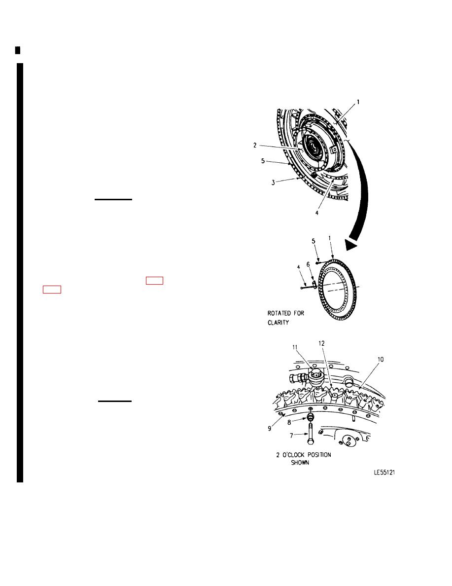
GAS TURBINE POWER UNIT REPLACEMENT (Sheet 9 of 30)
17. REMOVE MECHANICAL GUARD (1) FROM
POWER UNIT (2) AND REGENERATOR (3).
a.
Cut and remove safety wire from 45 bolts (4)
and 60 bolts (5).
b.
Remove 45 bolts (4), assess cover (6) and 60
bolts (5).
c.
Remove mechanical guard (1).
18. INSPECT MECHANICAL GUARD (1) FOR ELON-
GATED BOLT HOLES, WARPAGE OR CRACKS.
REPLACE AS REQUIRED.
CAUTION
Do not install four temporary bolts (7)
without spacers (8). Bolts may extend
beyond thread depth and become lodged
in power unit housing.
NOTE
Use four of the 45 bolts removed in step
17.b. Use four nuts (callout 14, page
module flange, as spacers (8).
19. TEMPORARILY INSTALL FOUR BOLTS (7) AND
SPACERS (8) WITH THE FIRST BOLT LOCATED IN A
BOLT HOLE NEAR THE END OF TURNBUCKLE ROD
BEARING ASSEMBLY (11). EVENLY SPACE OTHER
3 BOLTS 90 DEGREES APART (APPROXIMATELY 2,
4, 8 AND 10 O'CLOCK POSITIONS) ON MECHANI-
CAL HOUSING OUTER FLANGE (9). TIGHTEN
BOLTS SECURELY
CAUTION
Excessive rotation of spur gear (10), with
turnbuckle rod bearing (11) disconnected,
may cause vanes (12) to become un-
hinged from spur gear (10).
If vanes (12) become unhinged, reas-
semble turbine power unit with original
parts and replace rear engine module.
Go on to Sheet 9
6-70
Change 6
|
|
Privacy Statement - Press Release - Copyright Information. - Contact Us |
