 |
|||
|
|
|||
|
|
|||
| ||||||||||
|
|
 TM9-2835-255-34
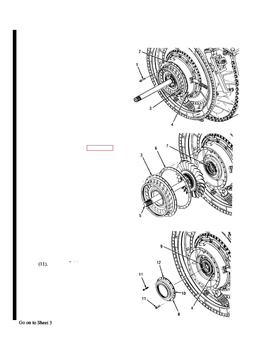
NO. 5 SEAL AND DIAPHRAGM ASSEMBLY REPLACEMENT (Sheet 2 of 7)
NOTE
Tighten three jackscrews (1) evenly opposite each
other.
3.
USING THREE BOLTS (1) AS JACK-
SCREWS, INSTALL BOLTS INTO THREE
THREADED HOLES (2). TIGHTEN
EVENLY UNTIL NOZZLE (3) IS AWAY
FROM POWER TURBINE HOUSING (4).
REMOVE THREE BOLTS (l).
4.
REMOVE SHAFT (5), NOZZLE (3) AND
SPACER RING (6).
5.
INSPECT NO. 5 BEARING (7) FOR
CORROSION, PITTING OR FRACTURE. IF
DAMAGE EXISTS, INSTALL SHAFT (5),
NOZZLE (3) AND SPACER RING (6)
USING OLD PARTS. REPLACE REAR
ENGINE SUBASSEMBLY (PAGE 6-28).
6.
REMOVE HOUSING ASSEMBLY (8) FROM
NO. 5 SEAL AND DIAPHRAGM ASSEM-
BLY (9).
a. With marker place a line (10) on housing
(8) and power turbine housing (4).
b. Soak 12 bolts (11) with penetrating oil. Cut
safety wire and remove 12 bolts.
NOTE
Tighten three jackscrews (11) evenly opposite each
other.
c. Using three bolts (11) as jackscrews,
install into three threaded holes (12).
Tighten evenly until housing (8) is away
from diaphragm assembly (9).
d. Remove housing (8). Remove three bolts
6-46 Change 4
|
|
Privacy Statement - Press Release - Copyright Information. - Contact Us |
