 |
|||
|
|
|||
|
Page Title:
NO. 5 SEAL AND DIAPHRAGM ASSEMBLY REPLACEMENT (Sheet 1 of 7) |
|
||
| ||||||||||
|
|
 TM 9-2835-255-34
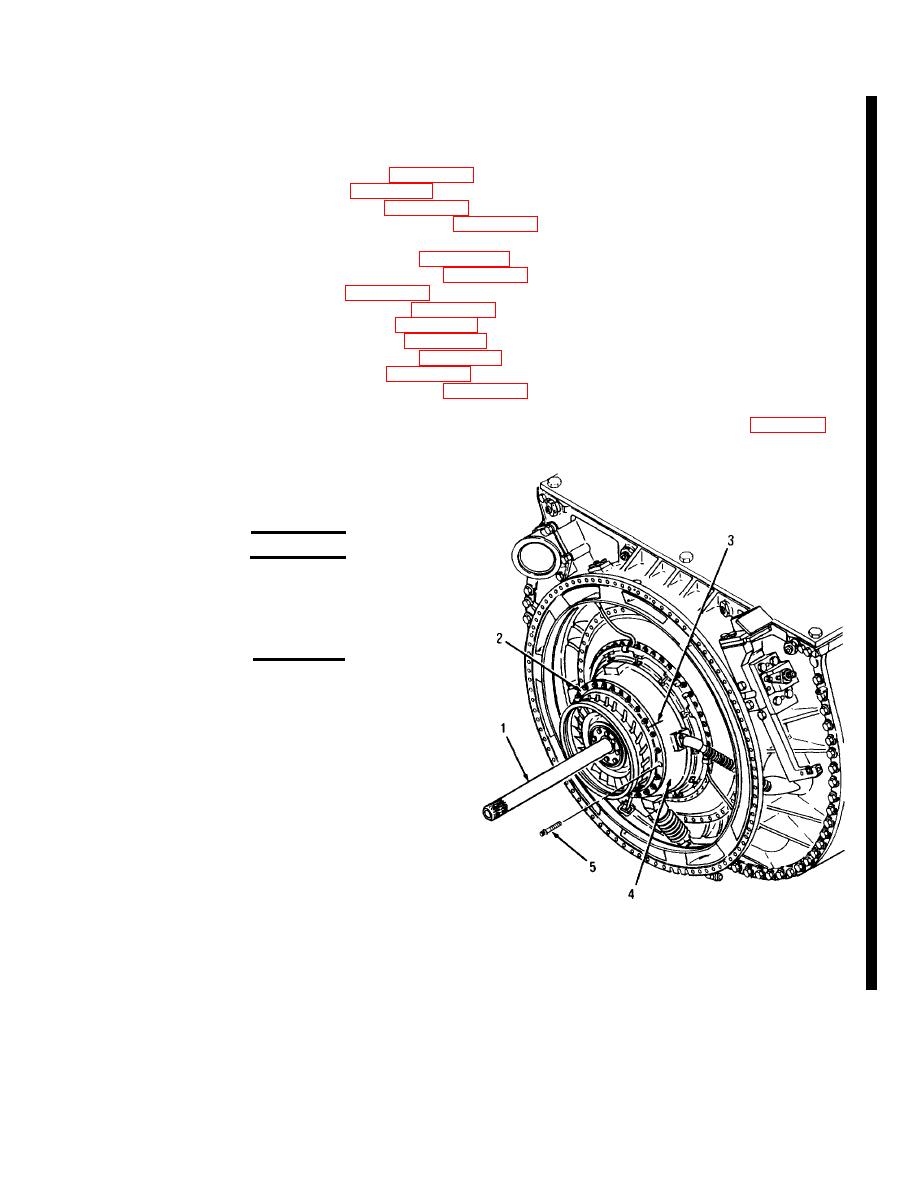
NO. 5 SEAL AND DIAPHRAGM ASSEMBLY REPLACEMENT (Sheet 1 of 7)
TOOLS: General mechanic's tool kit: automotive (SC5180-90-N26)
Industrial goggles (Item 58, Appendix D)
Press, arbor (Item 37, Appendix D)
Tool, No. 5 seal (Item 140, Appendix D)
Torque wrench, 0-150 lb-in (Item 27, Appendix D)
SUPPLIES:
Antiseize compound (Item 2, Appendix B)
Diaphragm assembly (Item 155, Appendix E)
Marker (Item 25, Appendix B)
Non-electric wire (Item 15, Appendix B)
Penetrating oil (Item 44, Appendix B)
Ring, retaining (Item 154, Appendix E)
Seal, plain, No. 5 (Item 126, Appendix E)
Seal, special (Item 127, Appendix E)
Shortening compound (Item 20, Appendix B)
EQUJPMENT CONDITIONS: Forward engine module (gearbox module attached) removed (page 5-25)
PERSONNEL: T WO
REMOVAL:
WARNING
Support turbine rotor shaft (1) and turbine nozzle (2)
when removing to prevent damage to parts and
injury to personnel.
CAUTION
Do not lean or hang anything on shaft (1). Damage
to bearing or seals may result.
1.
USING MARKER, PLACE A LINE (3) ON
NOZZLE (2) AND POWER TURBINE
HOUSING (4).
2.
REMOVE SHAFT (1) AND NOZZLE (2)
FROM POWER TURBINE HOUSING (4).
a. Soak 24 bolts (5) with penetrating oil.
b. Cut safety wire and remove 24 bolts (5).
NOTE
If nozzle (2) did not separate from turbine housing
(4), go to step 3. If nozzle separated from power
turbine housing (4). go to step 4.
Go on to Sheet 2
Change 4 6-45
|
|
Privacy Statement - Press Release - Copyright Information. - Contact Us |
