 |
|||
|
|
|||
|
Page Title:
TUBE ASSEMBLY (REDUCTION GEARBOX SCAVENGE - REAR) REPLACEMENT (Sheet 1 of 2) |
|
||
| ||||||||||
|
|
 TM 9-2835-255-34
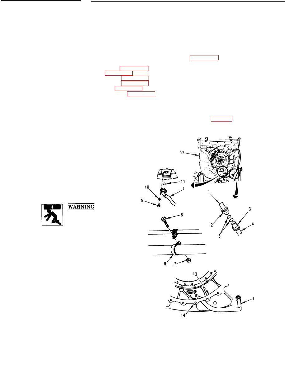
TUBE ASSEMBLY (REDUCTION GEARBOX SCAVENGE - REAR)
REPLACEMENT (Sheet 1 of 2)
TOOLS: General mechanic's tool kit: automotive (SC 5180-90-CL-N26)
Conduit style slip joint pliers with plastic jaw inserts (Item 31, Appendix D)
SUPPLIES: Antiseize compound (Item 2, Appendix B)
Lockwasher (Item 29, Appendix E) (2 required)
Preformed packing (Item 28, Appendix E)
Preformed packing (Item 30, Appendix E) (2 required)
Self-locking nut (Item 24, Appendix E)
Shortening compound (Item 20, Appendix B)
PERSONNEL: Three
EQUIPMENT CONDITION: Engine disconnected from transmission (TM 34-1)
Engine/rear module lifting sling installed on engine (page 4-4)
REMOVAL:
1. DISCONNECT TUBE (l).
a. Loosen tube fittings (2, 3) and remove
tube (1) from tube assembly (4). Remove
two preformed packings (5).
b. Remove screw (6), self-locking nut (7), and
clamp (8).
(10). Move tube (1) down and remove
preformed packing (11).
2. REMOVE TUBE (1).
a. Lift engine (12) enough to allow tube (1)
to be removed.
b. Hold engine (12) steady and remove tube
(1) through hole (13) in rear module (14).
c. Set engine (12) on maintenance stand.
3. INSPECT PARTS FOR DAMAGE. REPLACE
AS REQUIRED.
Go on to Sheet 2
6-8
|
|
Privacy Statement - Press Release - Copyright Information. - Contact Us |
