 |
|||
|
|
|||
|
|
|||
| ||||||||||
|
|
 TM 9-2835-255-34
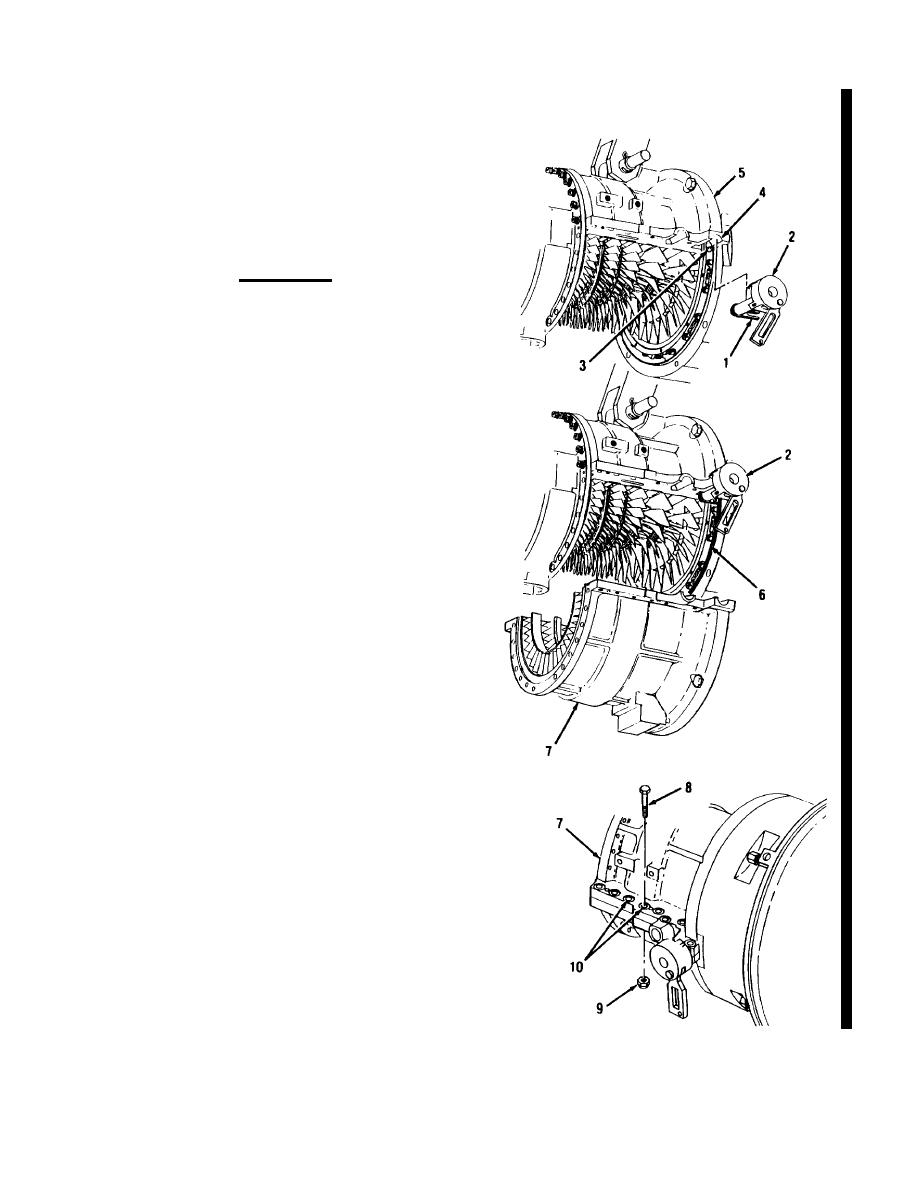
LOW PRESSURE ROTOR AND HOUSING ASSEMBLY (COMPRESSOR) AND HIGH PRESSURE
AXIAL COMPRESSOR AND ROTOR CLEANING (Sheet 18 of 21)
POSITION FORK END (1) OF BELLCRANK
35.
AND SHAFT (2) AROUUND BALL JOINT
(3), AND HOLD BELLCRANK AND SHAFT
(2) IN CUTOUT (4) OF LOW PRESSURE
CASE (TOP HALF) (5).
CAUTION
Packing (6) could get moved and pinched. Use care
when installing case and stator (bottom half (7) not
to move or pinch packing (6).
NOTE
Do not move bellcrank and shaft (2) when housing
(7) is installed. Fork end (1) will disconnect from
balljoint (3).
36. TURN BELLCRANK AND SHAFT (2) ALL
THE WAY TO THE RIGHT, AND INSTALL
LOW PRESSURE VANE AND STATOR
ASSEMBLY (BOTTOM HALF) (7). IN-
STALL NINE BOLTS (8) AND NINE NEW
NUTS (9).
a. Turn bellcrank and shaft (2) all the way to
the right.
b. Position vane and stator assembly (bottom
half) (7) on engine. Do not damage or
move packing (6).
NOTE
Only 9 of the 12 bolts (8) required are to be installed
at this time. Install bolts in two holes (10) only on
right side of case and stator assembly (7),
c. Apply antiseize compound to nine bolts
(8). Install nine bolts (8) and new nuts (9).
37. TORQ UE BOLTS (8) AND NUTS (9) BE-
TWEEN 100-110 LB-IN (11-12 N-m).
Go on to Sheet 19
Change 4 5-51
|
|
Privacy Statement - Press Release - Copyright Information. - Contact Us |
