 |
|||
|
|
|||
|
|
|||
| ||||||||||
|
|
 TM 9-2835-255-34
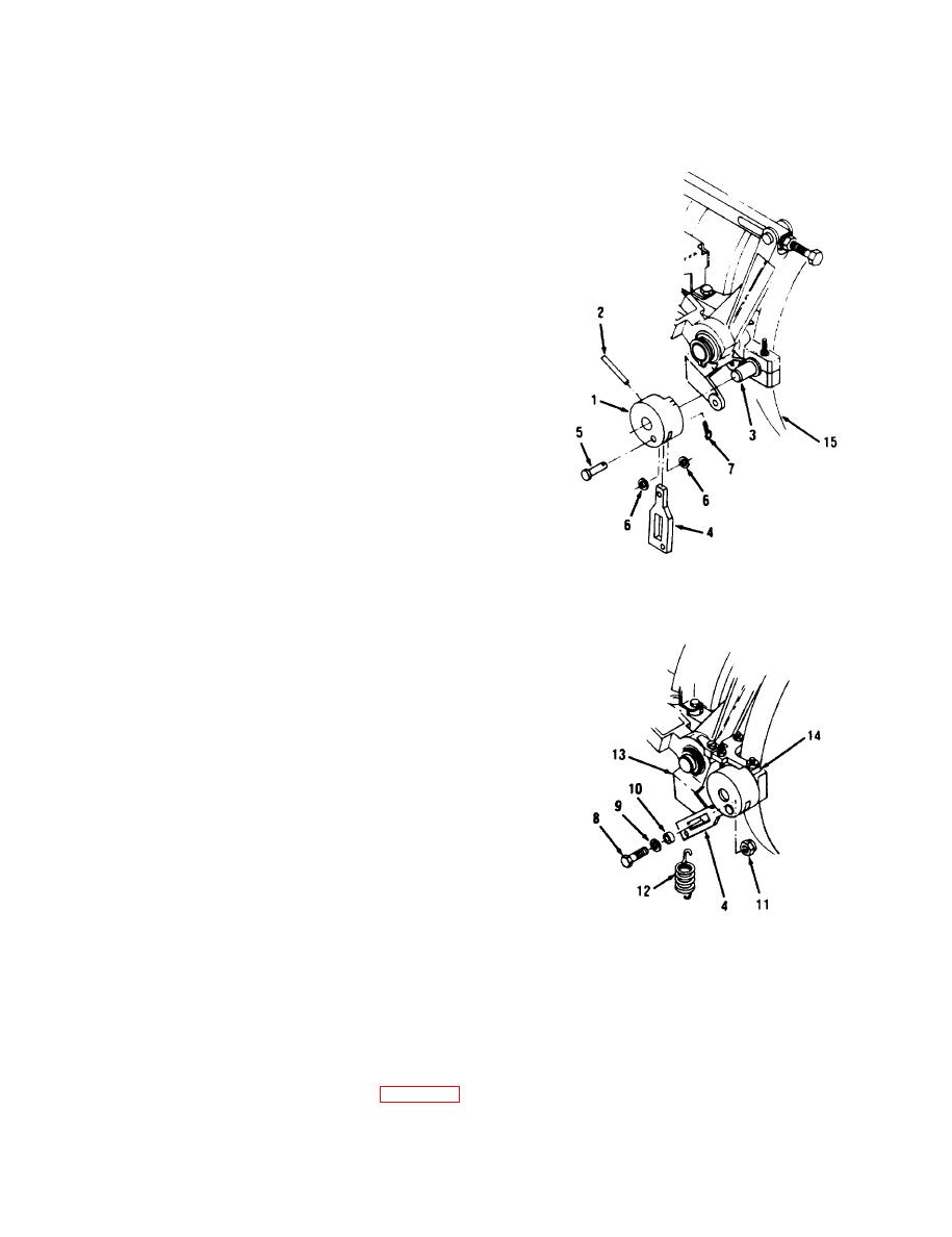
IGV BE1.LCRANK SPRING PIN REPLACEMENT (Sheet 2 of 2)
INSTALLATION:
PLACE BELLCRANK (1) ON FLAT
1.
SURFACE. START NEW PIN (2) INTO
BELLCRANK (1) WITH SLIT OF PIN (2)
FACING INWARD NOTCH.
NOTE
If pin (2) was removed with intermediate (low
q
pressure) housing (top half) installed, do steps 2
thru 7 only. lf not, go to step 8.
Use 3/32-inch punch to assist in alining pin (2)
q
until it seats. When fully seated, pin (2) should
extend about l/4-inch out of bellcrank (1).
INSTALL PIN (2) IN BELLCRANK (1) AND
2.
SHAFT (3).
INSTALL CONNECTING LINK (4).
3.
a. Install pin (5), two washers (6), and new
cotter pin (7) in link (4) and bellcrank (1).
b. Install screw (8), washer (9), spacer (10),
nut ( 11), and spring (12) in link (4) and
lever assembly (13).
INSTALL IGV STOP BRACKET (14).
4.
INSTALL INLET GUIDE VANE AC-
.5 .
TUATING CYLINDER (TM 20-l).
INSTALL TUBE ASSEMBLY (NUMBER 1
6.
BEARING FEED) (TM 20-1).
INSTALL SCREEN ASSEMBLY (ENGINE
7.
AIR INLET) (TM 20-l).
NOTE
Use 3/32- inch punch to assist in alining pin (2) until
it seats. When fully seated, pin (2) should extend
about 1/4-inch out of bellcrank (1).
8.
[NSTALL PIN (2) IN BELLCRANK (1) AND
SHAFT (3).
INSTALL BELLCRANK (1) AND SIIAFT (3)
9.
IN I.OWER HOUSING (15).
10. INSTALL INTERMEDIATE (LOW PRES-
SURE) HOUSING (TOP HALF) (PAGE 5-8).
End of Task
Change 4 5-33
|
|
Privacy Statement - Press Release - Copyright Information. - Contact Us |
