 |
|||
|
|
|||
|
Page Title:
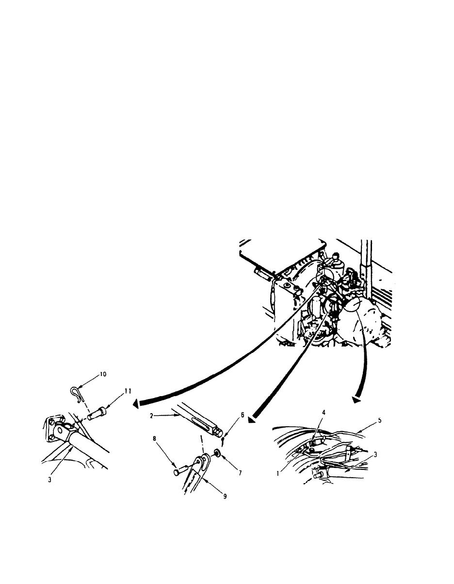
TURBINE AXIAL COMPRESSOR (HIGH PRESSURE) HOUSING (TOP HALF) REPLACEMENT (Sheet 2 of 5) |
|
||
| ||||||||||
|
|
 TM 9-2835-255-34
TURBINE AXIAL COMPRESSOR (HIGH PRESSURE) HOUSING (TOP HALF)
REPLACEMENT (Sheet 2 of 5)
EQUIPMENT CONDITION: Engine starter motor removed (TM 20-1)
Pressure fluid filter double angle bracket removed (TM 20-1)
Transmission pressure velocity modulator tube assembly removed
(TM 20-1)
Tube assembly (top of inlet guide vane actuating cylinder) removed
(TM 20-1).
Tube assembly (bottom of inlet guide vane actuating cylinder) removed
(TM 20-1)
Tube assembly (forward reduction gearbox) removed (TM 20-1)
Tube assembly (No. 5 and 6 bearings) removed (TM 20-1)
Tube assembly (No. 2 and 3 bearings) removed (TM 20-1)
Tube assembly (No. 2 and 3 bearing feed) removed (TM 20-1)
Inlet guide vane feedback control assembly removed (TM 20-1)
Compressed air tube assembly removed (TM 20-1)
Tube assembly (electro-mechanical fuel system to fuel nozzle) removed
(TM 20-1)
Ignition electrical lead removed (TM 20-1)
REMOVAL:
1. DISCONNECT ROTOR TEMPERATURE
SENSOR (1), STUD (2), AND RIG
CONNECTING LINK (3).
a. Remove connector (4) from sensor (1).
Move cable lead (5) away from link (3).
b. Remove cotter pin (6), washer, (7) and pin
(8). Move stud (2) out of lever (9). Set
stud (2) on engine.
c. Remove lockpin (10) and pin (11). Move
link (3) all the way forward,
Go on to Sheet 3
5-2
|
|
Privacy Statement - Press Release - Copyright Information. - Contact Us |
