 |
|||
|
|
|||
|
|
|||
| ||||||||||
|
|
 TM
9-2835-255-34
-
CONTINUED
3-2. TROUBLESHOOTING
1. SPEED CIRCUIT
(1) ES-45. ENGINE SPEED CIRCUIT
FAULTY.
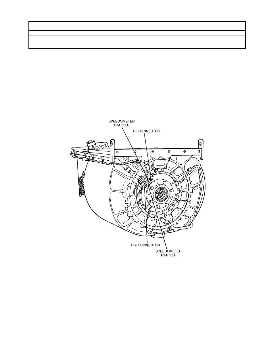
This section contains troubleshooting to determine and correct the
cause(s) of a faulty engine speed circuit. The engine output speed is
sensed by two independent speedometer adapters located on the rear cover
of the reduction gearbox (RGB) and coupled to the electronic control
unit (ECU) by an electrical cable. If both speedometer adapter circuits
a r e f a u l t y , engine output RPM will not be indicated and the ECU will
induce a protective mode of operation. The art on this page provides an
overview of the engine output speed circuit described above. Refer to
this page along with in-text art while doing troubleshooting.
Change 5
3-339
|
|
Privacy Statement - Press Release - Copyright Information. - Contact Us |
