 |
|||
|
|
|||
|
|
|||
| ||||||||||
|
|
 TM
9-2835-255-34
3-2. TROUBLESHOOTING - CONTINUED
E S - 2 5 . INLET GUIDE VANES (IGVs)
(1)
g. INLET GUIDE VANE (IGV)
DO NOT MOVE WHEN IGV BELLCRANK
SYSTEM
I S TURNED BY HAND.
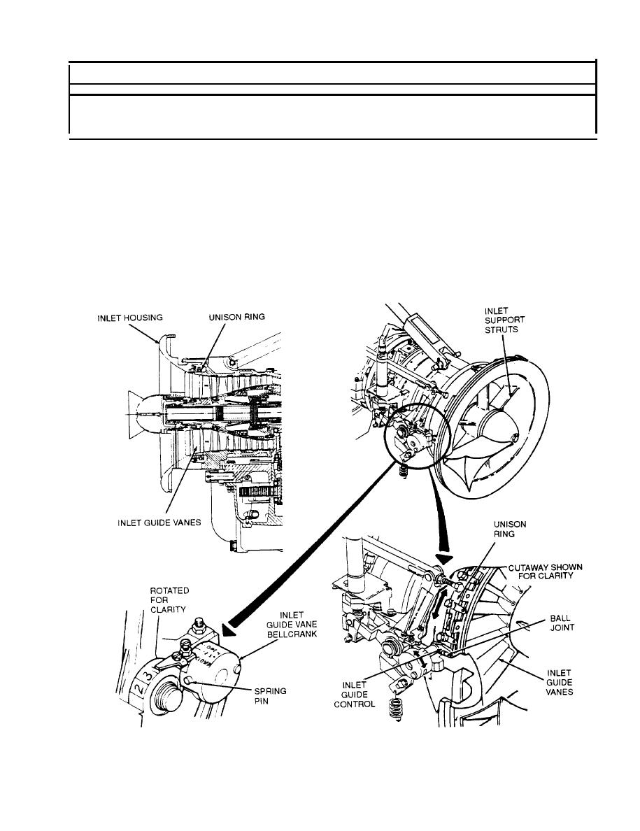
This section contains troubleshooting to determine why the IGVs do not
move when the IGV bellcrank is turned. The IGVs are located in the inlet
housing behind the inlet support struts. The }ndividual vanes are
c o u p l e d t o g e t h e r a n d c o n t r o l l e d b y a u n i s o n r i n g w h i c h IS c o n n e c t e d t o
t h e b e l l c r a n k o u t s i d e t h e e n g i n e t h r o u g h a n i n l e t g u i d e c o n t r o l: T h e
bellcrank is secured to the inlet guide control with a spring pin. If
the spring pin is loose or missing or if the forked area of the lnlet
guide control is worn or not engaged on the ball joint, the unison rlng
will not activate and the IGVs will not move. If the unison ring and/or
the IGVs are damaged or disconnected, the IGVs will not move when the
bellcrank is turned. The art on this page provides an overview of the
bellcrank and inlet guide vane parts. Refer to this page along w i t h i n -
text art while doing troubleshooting.
3-203
Change
|
|
Privacy Statement - Press Release - Copyright Information. - Contact Us |
