 |
|||
|
|
|||
|
Page Title:
Engine Idle Speed, Buffer Screw and Buffer Switch Adjustment. |
|
||
| ||||||||||
|
|
 TM 9-2815-224-34&P
Engine Tune-Up Instructions (Cont)
19-9.
ENGINE SPEED ADJUSTMENTS (CONT).
b.
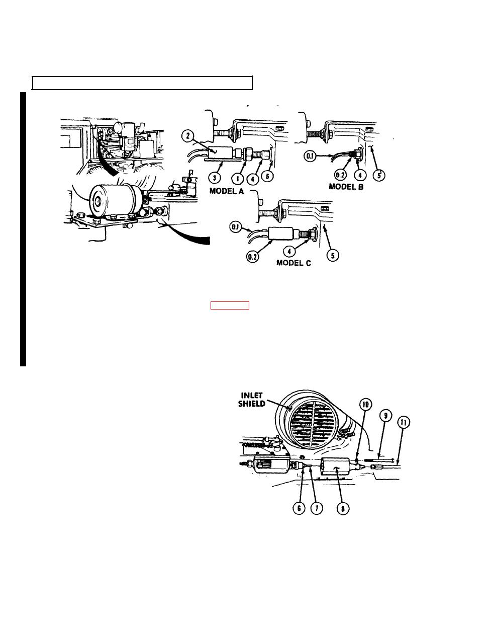
Engine Idle Speed, Buffer Screw and Buffer Switch Adjustment.
NOTE
There are three styles of buffer switches, Model A Model B and Model C.
l
Buffer screw and buffer switch will turn out with locknut.
l
Adjust maximum no-load engine speed (para 19-9).
(1)
NOTE
Perform step (1.1) for Model B and Model C buffer switches.
(1.1) Tag, mark and remove wires (0.1) from buffer switch (0.2).
NOTE
Perform step (2) for Model A buffer switch.
Loosen nut (1) and remove buffer switch (2)and bracket (3).
(3)
Loosen locknut (4) and back out to 0.65in. (15.88 mm) from governor housing (5).
Loosen locknut (6) from idle adjusting
(4)
screw (7).
When told by Soldier A, Soldier B starts
(5)
engine and operates for 15 minutes
(TM 9-2320-279-10).
I
NOTE
Correct engine idle speed is 675-725 rpm.
Turn idle adjusting screw (7) to correct
(6)
engine idle speed.
Tighten locknut (6) when correct engine
(7)
idle speed is reached.
When told by Soldier A, Soldier B stops
(8)
engine.
NOTE
Gasket is not replaced unless damaged.
(10) Install air hose (11) on cover (8).
(11) Remove inlet shield.
19-24 Change 2
|
|
Privacy Statement - Press Release - Copyright Information. - Contact Us |
