 |
|||
|
|
|||
|
Page Title:
BUFFER SCREW SWITCH REMOVAL/REPAIR/INSTALLATION. |
|
||
| ||||||||||
|
|
 TM 9-2815-224-34&P
Engine Governor Maintenance Instructions (Cont)
This task covers:
d. Assembly
a. Removal
e. Installation
b. Disassembly
f. Follow-on Maintenance
c. Cleaning/Inspection
INITIAL SETUP
References
Models
None
All
Equipment Condition
Test Equipment
Condition Description
TM or Para
None
TM 9-2320-279-20 Batteries disconnected.
Special Tools
TM 9-2320-279-10 Parking brake set.
None
TM 9-2320-279-10 Engine cover open.
Special Environmental Conditions
Supplies
Tags, identification, Item 61, Appendix C
None
General Safety Instructions
Oil, lubricating, Item 48, Appendix C
None
Personnel Required
Level of Maintenance
MOS 63W, Wheel vehicle repairer
Direct Support
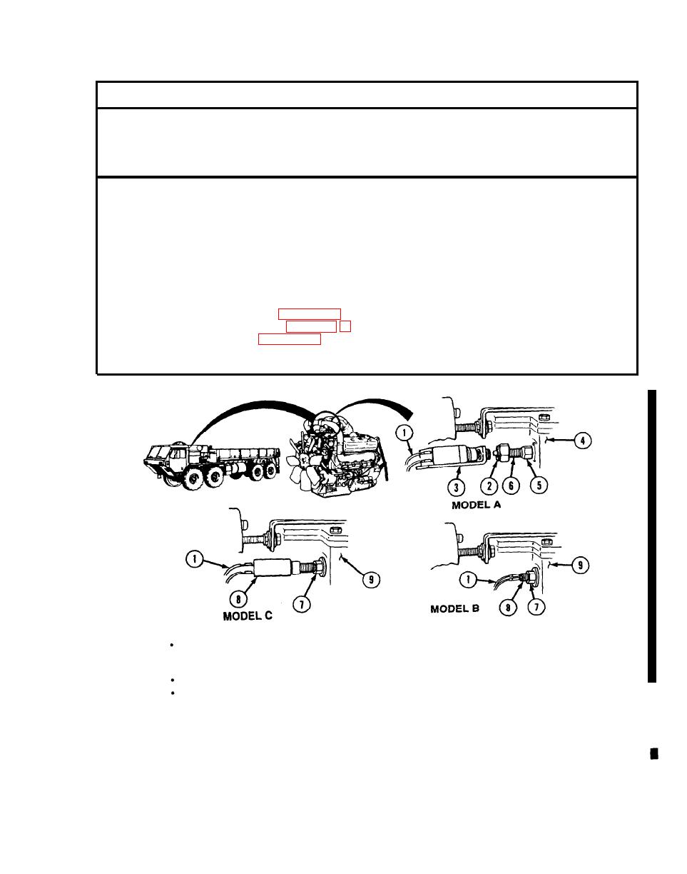
a. Removal.
NOTE
There are three models of buffer switches. Model A is square and has removable
parts. Model B is round and has no removable parts. Model C is square and has no
removable parts.
For Models B and C, do steps (l) and (5) only.
Tag and mark wires before disconnecting.
Disconnect two wires (1).
(1)
Loosen nut (2) and remove switch and bracket (3).
(2)
Measure and record distance buffer switch nut (2) extends from governor (4).
(3)
Loosen locknut (5) and remove screw (6).
(4)
Loosen locknut (7) and remove buffer switch (8) from governor (9).
(5)
Change 2
|
|
Privacy Statement - Press Release - Copyright Information. - Contact Us |
