 |
|||
|
|
|||
|
Page Title:
ENGINE BRAKE WIRE HARNESS REMOVAL/INSTALLATION. |
|
||
| ||||||||||
|
|
 TM 9-2815-224-34&P
Engine Brake Retarder Maintenance Instructions (Cont)
ENGINE BRAKE WIRE HARNESS REMOVAL/INSTALLATION.
This task covers:
c. Follow-on Maintenance
a. Removal
b. Installation
INITIAL SETUP
References
Models
None
All
Test Equipment
Equipment Condition
None
Condition Description
TM or Para
TM 9-2320-279-20 Batteries disconnected.
Special Tools
TM 9-2320-279-20 Rocker covers removed.
None
Special Environmental Conditions
Supplies
None
Connector, electrical butt, Item 34,
General Safety Instructions
None
Tags, identification, Item 61, Appendix C
Level of Maintenance
Personnel Required
Direct Support
MOS 63W, Wheel vehicle repairer
Removal.
a.
NOTE
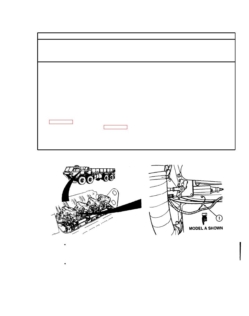
There are two models of engine brake wire harnesses. Model A has a wire extending
through the cylinder head and uses a butt connector to connect to the engine
harness. Model B has a spade (push-on) type connector. The following procedure
covers both models.
Engine brake wire harness is removed from left and right cylinder heads the same
way.
Tag and mark wires before removal.
Cut wire (1) for Model A. Disconnect wire (1) for Model B.
(1)
Change 2
|
|
Privacy Statement - Press Release - Copyright Information. - Contact Us |
