 |
|||
|
|
|||
|
|
|||
| ||||||||||
|
|
 TM 9-2815-224-34&P
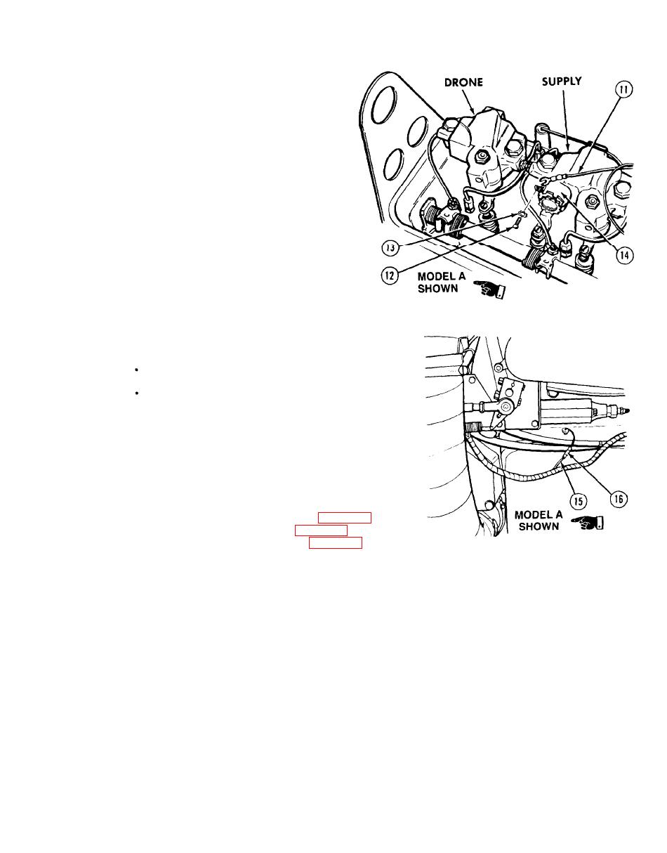
Engine Brake Retarder Maintenance Instructions (Cont)
Install solenoid valve wire (11),
(11)
screw (12), and lockwasher (13) on
solenoid valve (14) for Model A.
Connect wire (11) on engine brake
solenoid valve (14) for Model B.
Repeat steps (1) through (11) for
(12)
remaining supply brake and drone.
NOTE
Tag and mark wires before removal.
There are two kinds of engine brake wiring
harnesses. Model A has a wire extending
through the cylinder head and uses a "butt
type" connector while Model B has a "spade
type" connector. Model A is shown.
(13)
Connect engine brake wire (15) with butt
connector (16) for Model A, and connect
wire (15) for Model B.
c. Follow-on Maintenance.
Adjust exhaust valve clearance (para 19-2).
(1)
Adjust fuel injector timing (para 19-4).
(2)
Adjust engine brake retarder (para 19-3).
(3)
Install rocker covers (TM 9-2320-279-20).
(4)
Connect batteries (TM 9-2320-279-20).
(5)
Start and run engine for 10 minutes (TM 9-2320-279-10).
(6)
Turn on engine brake switch (TM 9-2320-279-10).
(7)
Open throttle to full engine speed and release.
(8)
Check engine brake operation when returning to idle.
(9)
Repeat full-throttle and release procedure six to eight times to bleed air from engine brake
(10)
system.
Shut off engine (TM 9-2320-279-10).
(11)
END OF TASK
11-5
Change 2
|
|
Privacy Statement - Press Release - Copyright Information. - Contact Us |
