 |
|||
|
|
|||
|
|
|||
| ||||||||||
|
|
 TM9-2815-224-34&P
Valve Mechanism Maintenance Instructions (Cont)
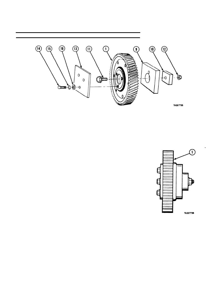
7-11. IDLER GEAR REMOVAL/REPAIR/INSTALLATION (CONT).
NOTE
To check idler gear pre-load, do steps (15) through (25).
(15) Mount idler gear (1) in soft jaw vise.
(16) Mount two test fixture plates (9 and 10) on idler gear (1) with screw (11) and nut (12). Tighten to
90 lb-ft (122 Nm).
washers (16). Tighten to 40 lb-ft (54 Nm).
(18) Place plate (10) in jaws of vise.
NOTE
Pull to start gear moving must not be less than 0.5 lb (0.23 kg) or more
than 4.0 lbs (1.8 kg).
(19) Wrap cord several times around idler gear assembly (1) and attach
spring scale.
(20) Pull idler gear assembly (1) several times and record pull required to
start gear moving. Maximum difference between pulls is 2 lbs,
11 ounces (1.22 kg).
(21) If difference between pulls does not fall in correct ranges, replace
7-40
|
|
Privacy Statement - Press Release - Copyright Information. - Contact Us |
