 |
|||
|
|
|||
|
Page Title:
EXHAUST VALVE BRIDGE REMOVAL/INSTALLATION. |
|
||
| ||||||||||
|
|
 TM 9-2815-224-34&P
Valve Mechanism Maintenance Instructions (Cont)
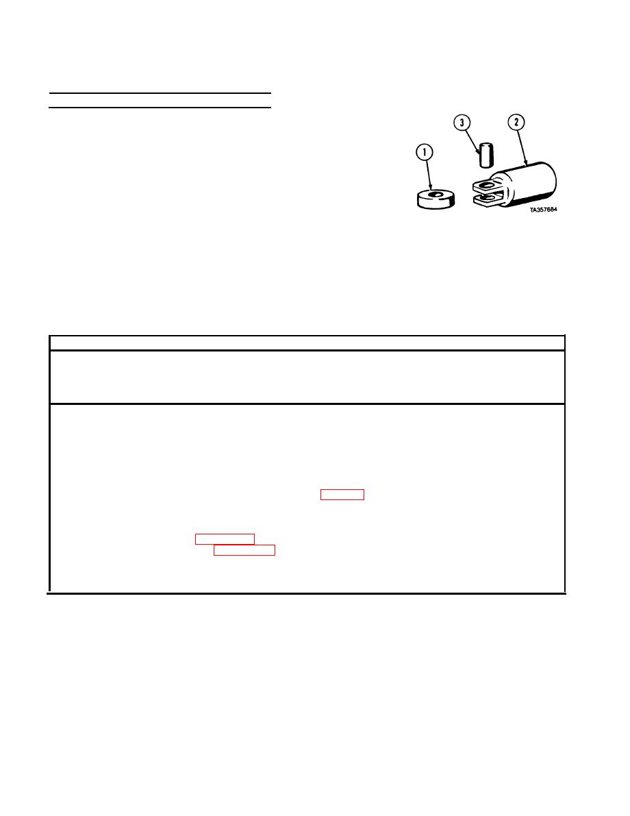
7-7. CAM FOLLOWER REPAIR (CONT).
c. Assembly.
NOTE
Apply lubricating oil to all parts before assembly.
(1) Install roller (1) in cam follower body (2).
(2) Install pin (3) through cam follower body (2) and roller (l).
(3) Check side clearance between cam follower body (2) and
roller (1) using feeler gage. Clearance must be between 0.011
and 0.023 in. (0.28 and 0.58 mm).
(4) Check pin-to-bushing clearance using dial indicator. Clearance must be less than 0.010 in.
(0.25 mm).
f. Follow-on Maintenance. N o n e .
END OF TASK
This task covers:
c. Follow-on Maintenance
a. Removal
b. Installation
INITIAL SETUP
References
Models
None
All
Equipment Condition
Test Equipment
None
Condition Description
TM or Para
Special Tools
Rocker arms removed.
Gage, feeler FB310B
Special Environmental Conditions
Supplies
None
Oil, lubricating, Item 48, Appendix C
General Safety Instructions
Tags identification, Item 61, Appendix C
None
Personnel Required
Level of Maintenance
MOS 63W, Wheel vehicle repairer
Direct Support
|
|
Privacy Statement - Press Release - Copyright Information. - Contact Us |
