 |
|||
|
|
|||
|
|
|||
| ||||||||||
|
|
 GOVERNOR AND CAMSHAFT ASSEMBLY REPAIR (CONTINUED)
NOTE
Install thrust washer (4) over gear end of camshaft.
E
Drive pin into required dimension. If less than
0.7812 inch, replace pin.
for one-half hour.
Heat camshaft gear (5) to
F
Install spacer (8) with three screws (9).
J
Install gear key (6).
G
Hold camshaft, gear end up, and install ten steel balls (10)
K
Install camshaft gear (5).
H
into spacer slots (8).
I
Check that governor pin (7) extends 0.7812 inch from cam-
Install governor cup (11) and retaining ring (12).
L
shaft gear (5).
M
governor pin (7).
Apply heavy grease (item 10, Appx C)
1
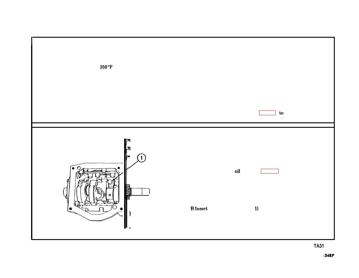
INSTALLATION
A Apply thin coat of
(item 16, Appx C) to each valve tappet.
NOTE
Make sure solid end of valve tappet faces
J
crankshaft.
four valve tappets
into valve tappet bores.
1223
3-115
TM 9-2815-221
|
|
Privacy Statement - Press Release - Copyright Information. - Contact Us |
