 |
|||
|
|
|||
|
|
|||
| ||||||||||
|
|
 *TM 9-2815-213-34
engine horsepower (288 H.P.) ] capacity is insufficient,
testing procedure must b modified to prevent damage to
the dynamometer
a. Using proper lifting device, place engine on
dynamometer test stand.
b. Position engine on the front engine support and
preselected risers for the rear engine supports; secure
engine mounting pads to engine support risers with bolts,
lockwashers and nuts. Remove lifting device.
c. Position dynamometer driveshaft flange to
engine flywheel. Use proper flywheel adapter flange to
match flywheel cap screw holes.
d. Check for proper alignment.
(1) If direct or flexible drive coupled, place a
dial gage holding fixture on face of flywheel housing and
dial gage on adapter flange hub; bar engine over to
obtain measurement. Relocate flange hub on flywheel
as needed and retighten cap screws. Flywheel adapter
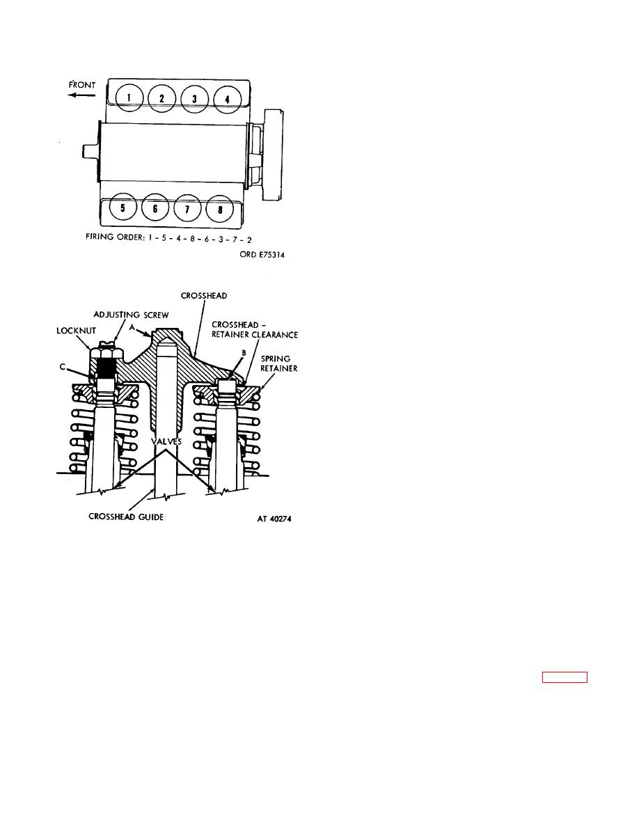
Figure 3-96. Engine firing order.
flange must be con- centric to flywheel and flywheel
housing within 0.005 inch total run-out. When using a
direct coupled dynamometer, a reading must be taken
from face of flywheel housing to outer edge of
dynamometer drive flange. It must not exceed 0.005
inch total run-out when barring dynamometer one
complete revolution.
(2) If universal drive coupled, flywheel and
dynamometer drive flanges must be concentric within
0.005 inch run-out; reading to be taken as above. Install
engine so that centerline of engine crankshaft and
centerline of dynamometer drive shaft are, by design,
out of plane either horizontally or vertically from 1/4 inch
minimum to 1/2 inch maximum. True alignment will
cause universal bearing failure. Secure flywheel to drive
flange with lockwashers and cap screws.
e. Connect water supply and return hose to the
water cooling arrangement.
f. Attach fuel pump return line, if used.
g. Attach fuel supply line to fuel pump suction
connection.
h. Connect electrical connections to starting motor
if motor is used for starting. If another means of starting
Figure 3-97. Crosshead adjustment.
is used make necessary connections.
i. Connect throttle linkage and all instruments
essential because it provides an operating period during
which are included on the control panel of the particular
which coving parts acquire their finish and mating
dynamometer being used.
surfaces reach a full seat. Engine testing helps detect
j. Connect exhaust piping to engine exhaust
possible assembly errors an the need for adjustments as
manifold.
engine "breaks-in as well as establishing a period for
k. Connect air intake piping to air intake manifold.
final adjustments for best engine performance.
A
Use a standard air cleaner approved for the V8300
dynamometer provides the simplest and most accurate
engine.
tool for testing and breaking in an engine. (Follow the
l. Connect a full flow lubricating oil filter to remove
instructions in sequence below for pr starting checks,
any entrapped dirt or grit.
dynameter mounting,
engine starting,
testing,
m. Install a Blow-By Checking Tool (3, fig. B-28) to
adjustments and break-in.
the crankcase breather with adapter.
3-169. Dynamometer Test
Check the capacity of the dynamometer. The stand
must be capable of testing at 96 percent c maximum
3-59
|
|
Privacy Statement - Press Release - Copyright Information. - Contact Us |
