 |
|||
|
|
|||
|
Page Title:
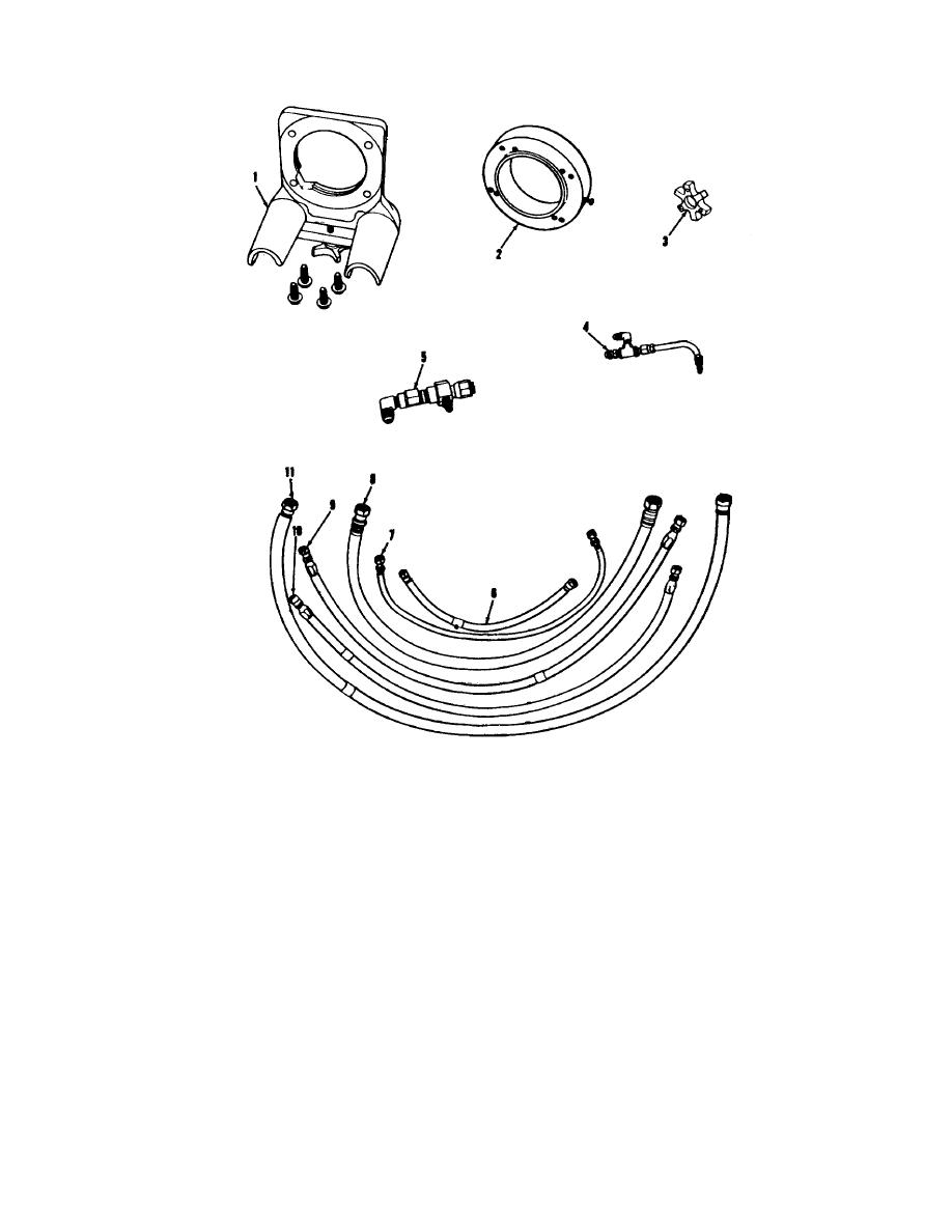
Figure 3-79. Fuel pump test stand equipment. |
|
||
| ||||||||||
|
|
 *TM 9-2815-213-34
1 Adapter bracket (11020392)
7 Fuel manifold hose (11020361-10)
2 Adapter ring assembly (11020532)
8 Fuel suction hose (110203613)
3 Coupling insert (110200539)
9 Fuel input hose (11020361-11)
4 Discharge fitting assembly (11020540)
10 Fuel pressure hose (11020361-14)
5 Leakage accumulator hose (11020361-10)
11 Fuel return hose (11020361-12)
6 Leakage accumulator hose (11020361-10)
Figure 3-79. Fuel pump test stand equipment.
Gasket). Move depth gage to opposite side of carrier and
down to plunger.
(b) Subtract second measurement from average
again measure to front cover gasket surface directly
across cover from previous measurement (do not turn
determined under (b) above. The result is the weight
carrier or cover). Average these two measurements. This
assist protrusion. If weight assist protrusion is below
procedure is necessary to determine uneven carrier wall
specifications, (0.840/0.860), add shims on reassembly.
heights.
If weight assist protrusion is above specifications,
(c) Position depth gage across carrier directly over
remove shims or grind exposed end of weight assist
weight assist plunger. Measure
plunger.
(4) Pump Gear Assembly.
3-42
|
|
Privacy Statement - Press Release - Copyright Information. - Contact Us |
