 |
|||
|
|
|||
|
Page Title:
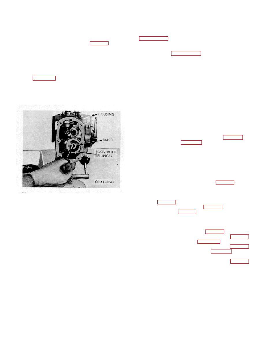
Figure 3-78. Plunger assembly-removal/installation. |
|
||
| ||||||||||
|
|
 *TM 9-2815-213-34
sleeve (7), and gear (8) from housing.
3-103. Cleaning
(d) Press the gear from shaft and remove bearing
Clean all fuel pump components in accordance with
sleeve.
3-104. Inspection
(1) Filter Assembly.
a. Visual. Visually inspect the assembled pump in
(a) Remove filter cap (3), sealing ring (2), filter
accordance with paragraph 2-6.
spring (4), and filter element (5).
b. Housing Porosity and Leakage Check.
(b) Discard sealing ring.
(1) Fill fuel pump with clean diesel fuel.
(2) Governor Plunger Assembly.
(2) Remove suction fitting at fuel pump gear
(a) Remove plunger assembly from housing as
assembly and install suitable air fitting to facilitate
shown in figure 3-78.
attaching 20 psi. air pressure hose.
(b) Remove spring pack housing (31).
(3) Apply 20 psi maximum air pressure to fitting.
(c) Remove pin (36) securing drive governor
(4) Pour fuel oil over pump and examine for leaks
indicated by air bubbles.
plunger (16) tc plunger spacer (37) and shaft (35).
(d) Remove compression spring (33), shims (34),
(5) Wipe pump dry and check for seepage of fuel oil
from inside pump.
and thrust washer (38).
(6) If either type of leak is evident, fuel pump
housing must be replaced.
(7) Remove air hose and fitting.
(8) Replace suction fitting on fuel pump gear
assembly.
c. Mounting Pump On Test Stand.
(1) Mount adapter ring assembly (2, fig. 3-79) to
adapter bracket (1, fig. 3-79) and secure with four
capscrews and plain washers.
NOTE
"TOP" or part number on adapter ring
must be at top.
(2) Place ring and adapter assembly on stand mounting
rails and secure to rails with clamp bar (fig. 3-80). Finger
tighten clamp bar only.
(3) Mount pump on adapter ring and bracket
Figure 3-78. Plunger assembly-removal/installation.
assembly and secure with four capscrews and flat
washers (fig. 3-81).
(3) Throttle Assembly.
(4) Place coupling insert (3, fig. 3-79) into coupling
(a) Remove two throttle adjusting jam nuts (6) and
in stand drive shaft (fig. 3-81).
two adjusting screws (7).
(5) Loosen bar clamp and slide pump and bracket
(b) Remove throttle snap ring (17).
assembly to engage stand drive shaft. Allow 1.16-inch
(c) Cut seal wire (24) and remove throttle cover seal
end clearance between pump drive and stand drive.
(23).
Tighten bar clamp screw securely (fig. 3-82).
(d) Pull throttle assembly from housing
(6) Install pump inlet adapter assembly (5, fig. 3-79)
(e) Remove nut (22), lockwasher (21), flat washer
in pump inlet port as shown in figure 3-82.
(20), and capscrew (19) securing throttle lever (18) to
(7) Connect 1/2-inch ID flexible hose (11, fig. 3-79)
shaft.
from stand suction control valve (fig. 3-82) to flare
(f) Remove shaft cover (16), spacer (15), and stop
connector of inlet adapter assembly on pump.
pin (14) from shaft (13).
(8) Connect 1/4-inch clear flexible hose (7, fig. 3-79)
(g) Remove setscrew (8), lockwasher (9), plunger
from stand supercharger inlet con-
(10), shim (11), and O-Ring (12) from shaft.
(4) Remove pipe plug (27), clip (28), fuel body plug
(43), O-Ring (42), and pipe plug (1) from pump housing.
3-40
|
|
Privacy Statement - Press Release - Copyright Information. - Contact Us |
