 |
|||
|
|
|||
|
Page Title:
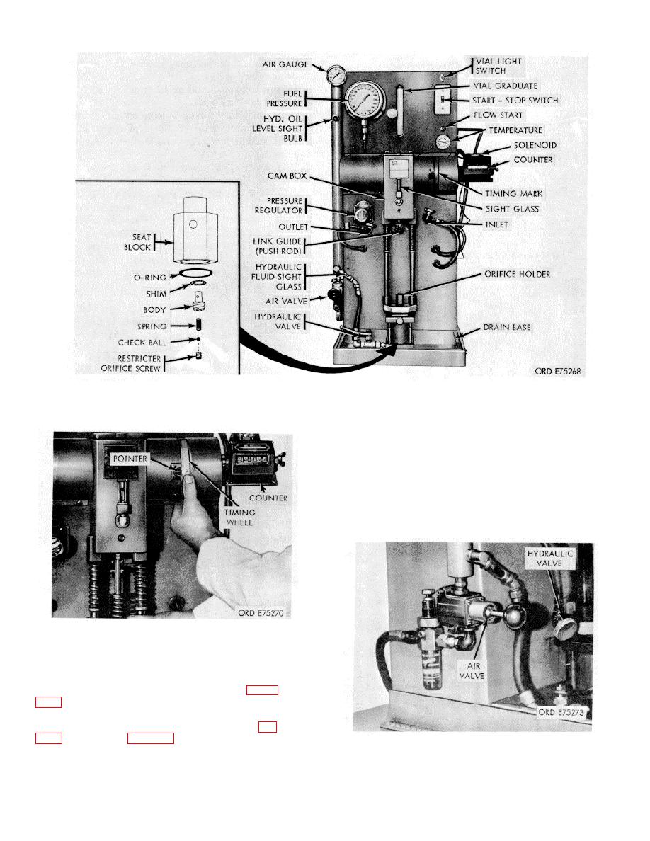
Figure 3-59. Injector test stand |
|
||
| ||||||||||
|
|
 *TM 9-2815-213-34
Figure 3-59. Injector test stand
(6) Remove plunger assembly and spring from
injector.
(7) Select correct size plunger bore plug and rubber
seal and install in injector plunger bore
(8) Install the solid knurled plug (fig.
65) in the injector drain opening.
(9) Place injector in spray angle tester seat (fig. 3-
65) and adjust hold-down bracket to position required, then
tighten thumb screw.
(2) Attach drain hose to tester base and place loose
end in test stand drain pan.
(3) Assemble 2 degree cup seat and space
to seat bracket bore.
(4) Check cup markings as shown in figure
hole target ring in base.
(5) Insert injector in injector adapter (2' fig.
Figure 3-61. Hydraulic and air valves.
3-29
|
|
Privacy Statement - Press Release - Copyright Information. - Contact Us |
