 |
|||
|
|
|||
|
Page Title:
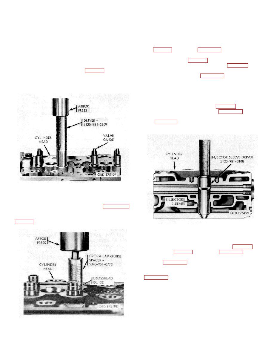
Figure 3-38. Valve guide installation |
|
||
| ||||||||||
|
|
 TM 9-2815-213-34
(2) Ream crosshead guide bore to 15/82 inch if
CAUTION
necessary after installation.
Insure that the 1/16 inch hole in valve
c. Injector Sleeves.
guide is turned toward exhaust manifold
(1) Install injector sleeves using sleeve driver
and that the hole remains open after
(14, fig. B-28) as shown in figure 3-40.
assembly.
(2) Remove injector sleeve driver and install
injector sleeve holder (fig. 3-30).
(1) Install valve guides as shown in figure 338.
(3) Using sleeve expander (13, fig. B-28), roll
Press in valve guide to 0.695/0.710 inch above head
upper portion of injector sleeve to 1.145/1.155 inches
surface with valve guide driver (49, fig. B-28).
inside diameter as shown in figure 3-41.
(2) Ream valve guide from bottom side of
NOTE
cylinder head using reamer, drill press and floating tool
holder. Valve guide must have inside diameter of
Set drill press at 250 rpm and 600
0.4525/0.4532 inch after reaming.
pounds pressure for 30 seconds; apply
OE-10 oil during operation.
(4) Remove injector sleeve holder.
(5) Using sleeve roller (16, fig. B-28), roll lower
portion of injector sleeve as shown in figure 3-48.
(6) Cut injector sleeve seat with sleeve cutter
(17, fig. B-28) as shown in figure 343, to provide
maximum allowable sleeve protrusion of 0.125 inch,
0.100/0.115 inch nominal.
Figure 3-38. Valve guide installation
b. Crosshead Guides.
(1) Install crosshead guides as shown in figure 3-39.
Press in crosshead guide to 2.090/
2.110 inches above head surface with guide spacer (47,
Figure 3-40. Injector sleeve installation.
d. Valve Seat Inserts.
(1) Recondition valve seat counterbore using tool
kit, cutter, and valve guide (48, 51 and 41, fig. B-28) to
proper size (A, fig. 3-36), as shown in figure 3-44.
(2) Install swirl plate in intake valve ports only as
shown in figure 3-45.
(3) Install valve seat insert using valve seat insert
tool kit and peen insert in cylinder head as shown in
e. Grind Valve Seats.
(1) Select a suitable valve grinding machine
Figure 3-39. Crosshead guide installation.
3-20
|
|
Privacy Statement - Press Release - Copyright Information. - Contact Us |
