 |
|||
|
|
|||
|
|
|||
| ||||||||||
|
|
 TM 9-2815-213-34
3-22. Repair
e. Install cover and secure with lockwashers and
No repair procedures beyond those specified paragraph
capscrews. Tighten capscrews to 30 to 35 foot-pounds
3-23. Installation
a. Position front cover with new gasket to block
Secure snugly with lockwashers and capscrews.
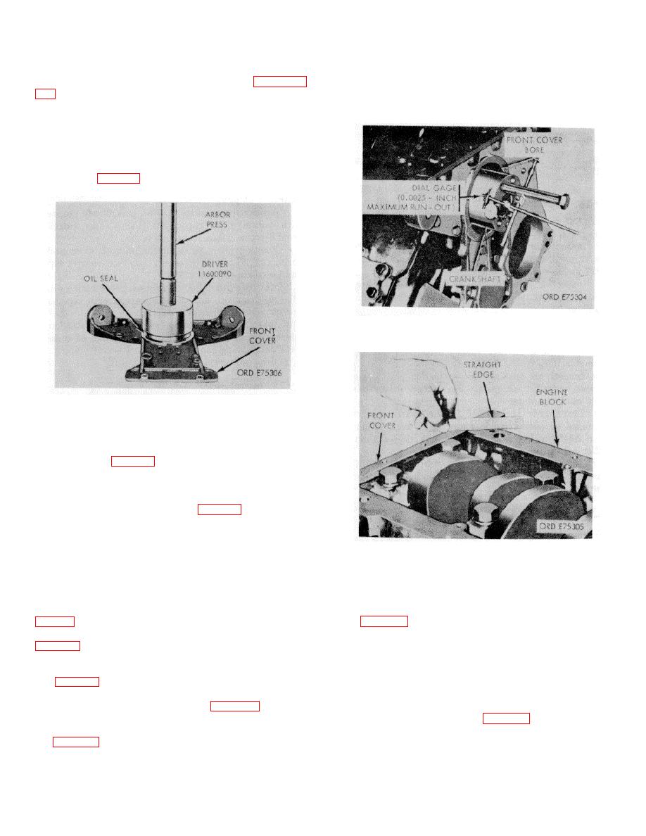
b. Place dial indicator gage on crankshaft with dial
pointer inside front cover bore. Rotate crankshaft and
check total indicator reading. Run-out must not exceed
0.0025 inch (fig. 3-15).
Figure 3-15. Front cover bore alinement check
Figure 3-14. Crankshaft oil seal-removal/installation.
c. Check that the bottom of the front cover and
cylinder block are level with a straight edge. There must
be no variation (fig. 3-16).
d. Remove front cover and press in new oil seal (3-
14).
(1) Position seal with open lip to inside.
(2) Use oil seal driver (38, fig. B-28) and arbox
press for pressing operation.
Figure 3-16. Front cover to block alinement check.
Section VI. Repair of Oil Pump Assembly
dowels in pump body. Discard gasket (3).
3-24. Disassembly
f. Remove six capscrews and lockplates (32 and
a. Remove two capscrews and lockplates (11 and
33, fig. B-10) securing scavenger pump body (2) to oil
pump body. Tap scavenger pump body to remove from
b. Remove four capscrews and lockplates (11 19,
dowels in oil pump body.
NOTE
gasket (17).
c. Remove three capscrews and lockplates (11 and
Gears and shafts will be removed
12, fig. B-9) securing suction tube to pump. Discard
from the pumps only in inspection
gasket (21).
warrants.
d. Remove four capscrews. (15, fig. B-10) securing
cover plate (16) to pump cover (20). Remove plate
g. Remove idler gear (31, fig. B-10) from shaft (30)
e. Remove four capscrews and lockplates (18 and
in scavenger pump body.
19, fig. B-10) securing pump cover to oil pump body (9).
h. Using a suitable puller; pull drive gear (17, fig.B-
Tap cover with soft head hammer to remove from
10) from cover.
3-9
|
|
Privacy Statement - Press Release - Copyright Information. - Contact Us |
