 |
|||
|
|
|||
|
Page Title:
Figure 2-9. Intake manifolds fuel pump and fuel lines--removal/installation. |
|
||
| ||||||||||
|
|
 *TM 9-2815-213-34
Figure 2-8.
Air intake crossover and preheater assembly--removal/installation.
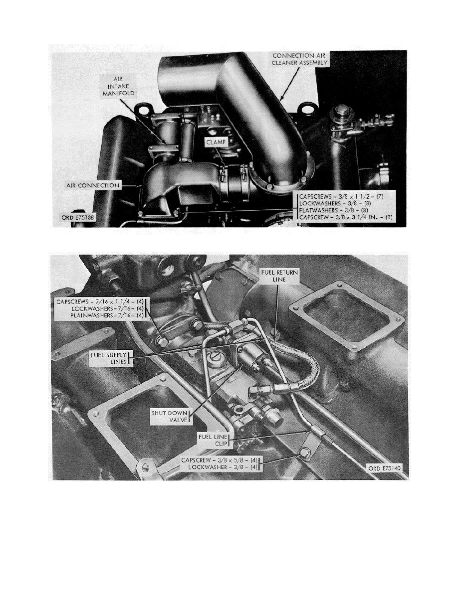
Figure 2-9. Intake manifolds fuel pump and fuel lines--removal/installation.
l. Fuel Pump and Fuel Lines (fig. 2 9).
(3) Disconnect fuel supply lines from cylinder heads
(front end).
(1) Disconnect flexible fuel drain return line at fuel
(4) Loosen fuel supply line clips securing lines to push
pump.
rod cavity covers, and remove lines.
(2) Disconnect two fuel supply lines at shutdown valve.
(5) Disconnect fuel drain crossover line at
2-7
|
|
Privacy Statement - Press Release - Copyright Information. - Contact Us |
