 |
|||
|
|
|||
|
Page Title:
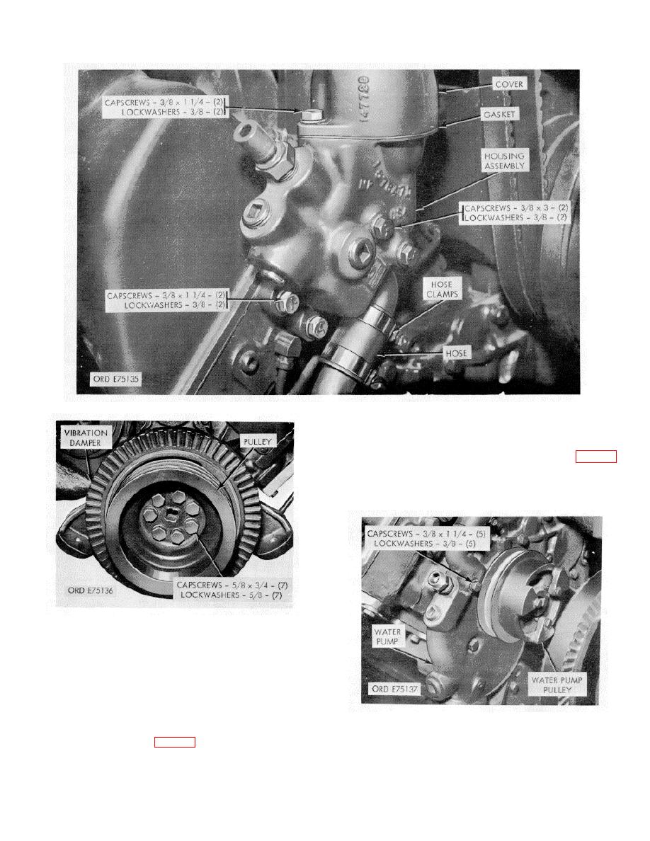
Figure 2-5. Thermostat assembly--removal/installation. |
|
||
| ||||||||||
|
|
 *TM 9-2815-213-34
Figure 2-5. Thermostat assembly--removal/installation.
and flat washers securing each manifold to each cylinder
head.
(2) Remove manifolds and gaskets.
10).
(1) Remove eight capscrews and lockwashers
securing crossover and lifting eyes to cylinder heads.
(2) Remove crossover, lifting eyes, and two gaskets.
Figure 2-6. Drive pulleys and vibration damper-
removal/installation.
(1) Loosen hose clamps on crossover to air
compressor flexible hose connection.
(2) Remove eight capscrews, lockwashers, and flat
washers securing crossover and preheater assembly to
intake manifolds.
(3) Disconnect flexible hose at air compressor and
Figure 2 7. Water pump assembly--removal/installation.
remove crossover and preheater assembly from
manifolds. Remove and discard two gaskets.
(1) Remove eight capscrews, lockwashers,
2-6
|
|
Privacy Statement - Press Release - Copyright Information. - Contact Us |
