 |
|||
|
|
|||
|
Page Title:
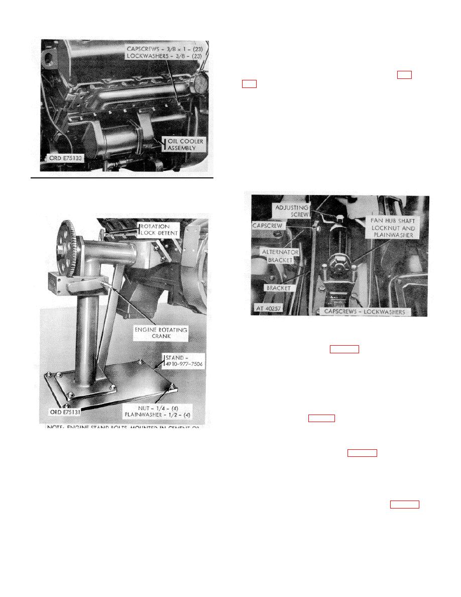
Figure 2-2. Oil cooler and cover plate--removal/installation. |
|
||
| ||||||||||
|
|
 *TM 9-2815-213-34
curing fan assembly mounting bracket to pump mounting
bracket.
(5) Remove pump assembly mounting bracket.
(1) Loosen fan hub shaft and back-off adjusting
screw to relieve belt tension.
(2) Remove belts from crankshaft pulley.
(3) Remove shaft locknut and washer.
(4) Pull fan and hub assembly forward to remove
from bracket. Remove washer from shaft.
(5) Remove six capscrews and lockwashers
securing bracket to engine block.
(6) Remove two capscrews and lockwashers
securing bracket to alternator and hydraulic pump
brackets and remove bracket.
Figure 2-2. Oil cooler and cover plate--
removal/installation.
Figure 2-4. Fan hub and bracket assembly--
removal/installation.
f.
Thermostat Assembly (fig. 2-5).
(1) Loosen clamp securing water pump hose to
thermostat housing.
(2) Remove four capscrews and lockwashers
securing assembly to cylinder head.
(3) Remove thermostat assembly and assembly to
cylinder head gasket.
g. Fan Drive Pulley, Vibration Damper, and Water-
(1) Remove seven capscrews and lockwashers
Figure 2-3. Eligible rebuild stand--removal/installation.
securing drive pulley and vibration damper to crankshaft.
(2) Remove pulleys and vibration damper.
(1) Remove capscrew and lockwasher securing belt
tension adjusting arm to pump bracket.
(1) Remove five capscrews and lockwashers
(2) Remove two mounting bolts securing hydraulic
securing water pump assembly to block.
pump and bracket assembly to main mounting bracket,
(2) Remove pump assembly by pulling straight
and remove assembly.
forward so impeller clears block. Remove and discard
(3) Remove three capscrews, lockwashers, and flat
gasket.
washers securing bracket to engine block.
(4) Remove capscrew and lockwasher se-
2-5
|
|
Privacy Statement - Press Release - Copyright Information. - Contact Us |
