 |
|||
|
|
|||
|
Page Title:
INSTALLATION OF INJECTION PUMP DRIVEN GEAR ACCESS COVER, FRONT CYLINDER HEAD COVER, AND CRANKCASE BREATHER ADAPTER |
|
||
| ||||||||||
|
|
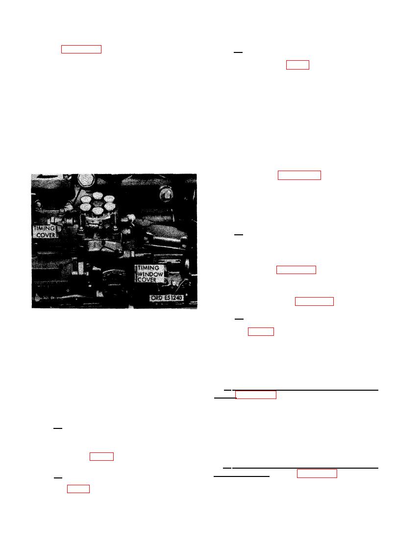 (7) Figure 501. (A) Position injection pump
(-c-) The marked tooth on the pump plunger
automatic advance unit timing cover on
drive gear is visible through the tim-
advance unit opening using a new gas-
ing window (fig. 65).
ket. (B) Secure timing cover with four
1/4- inch lock washers and 1/4 x 5/8
(2) Turn the crankshaft counterclockwise,
machine screws. (C) Position timing
as viewed from the fan end, approxi-
window cover over opening in fuel in-
mately 45 degrees. Turn crankshaft
jection pump assembly using a new
clockwise until timing mark on vibra-
gasket. (D) Secure cover with two 1/4-
tion damper is alined with the timing
inch lock washers and 1/4 x 1- 1/4 fil-
pointer on the camshaft gear cover. If
lister-head screws. (E) Connect fuel
the timing marks on the automatic
injection pump oil inlet hose to special
advance unit hub and pump plunger
tee connection in automatic advance
drive gear are not alined, recheck
unit.
engine timing and pump timing as fol-
lows.
Refer to figure 499 and reverse the
sequence of instructions to remove fuel
injection pump driven gear. It is not
necessary to remove injection pump.
Check injection pump timing as di-
rected in paragraph -- above.
a
(b) Check engine timing as directed in
paragraph b above.
Install fuel injection pump driven gear
and retaining plate following instruc-
tions for figure 499.
Set fuel injection pump timing in re-
lation to engine timing following in-
structions for figure 500.
(e) After timing is correct, install timing
covers and connect oil inlet hose
TIMING WINDOW COVER, AND CON-
NECTING FUEL INJECTION PUMP OIL
INLET HOSE.
DRIVEN GEAR ACCESS COVER, FRONT
CYLINDER HEAD COVER, AND CRANK-
d. Check Alinement of Fuel Injection Pump
CASE BREATHER ADAPTER
and Engine Timing Marks.
a. Install Injection Pump Driven Gear Access
(1) The engine and fuel injection pump are
Cover. Figure 502. (A) Position new driven gear
properly timed when the following con-
access cover gasket on timing gear cover, with
ditions can be observed.
stud and cap screw holes alined. (B) Position
driven gear access cover over gasket.(C) Install
(a) The timing mark on the vibration
three 3/8- inch lock washers and 3/8- inch plain
damper is alined with the timing
nuts on studs. (D) Install two 3/8 x 3-3/4 cap
pointer on timing gear cover and the
screws, 3/8- inch lock washers, and 3/8- inch
No. 1 cylinder is on its compression
plain nuts to secure cover.
stroke (fig. 63).
b. Install Flywheel Timing Cover (Early
Model Engines). Refer to figure 256 and reverse
(b) The automatic advance unit hub tim-
steps E and F and install flywheel timing cover.
ing mark is alined with its pointer
Use a new cover gasket.
318
|
|
Privacy Statement - Press Release - Copyright Information. - Contact Us |
