 |
|||
|
|
|||
|
Page Title:
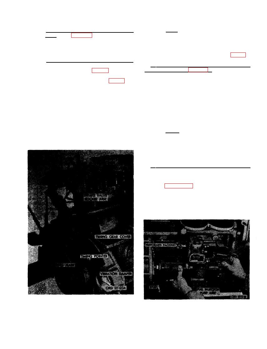
FIGURE 494. CHECKING ENGINE TIMING PRIOR TO FUEL INJECTION PUMP INSTALLATION. |
|
||
| ||||||||||
|
|
 Note. The injection pump camshaft and
(4) Install fuel injection pump driven gear
plunger spring assembly pressure tends
h u b . Refer to figures 72 and 73 and re-
to prevent timing mark on hub from re-
verse the sequence of instructions to
maining in line with its mating pointer.
install the fuel injection pump driven
These marks must be alined when instal-
gear hub.
ling injection pump driven gear (fig. 77).
(5) Timing fuel injection pump assembly.
b . Check Engine Timing Before Installing
T h e timing mark on the automatic
Fuel Injection Pump (fig. 494).
advance unit hub (fig. 64) must be
alined with pointer when the marked
(1) Rotate crankshaft clockwise, as viewed
tooth in the timing window (fig. 65) is
from fan end, until cylinder No. 1 intake
visible. It is possible to have the tim-
and exhaust valves are closed. When
ing marks in the advance unit alined
valve clearance is evident at both rocker
and not have the marked tooth on the
arms, both valves are closed.
plunger drive gear in the timing window
visible. When the marked tooth is visible
(2) The timing mark on the vibration dam-
and the advance unit marks are alined,
per and pulley assembly must be alined
the pump is properly timed. If the
with the pointer on timing gear cover.
marked tooth is not visible, rotate the
gear hub 360 degrees, in either direc-
tion, so the timing marks do aline. This
N o t e . The engine is properly timed
insures proper timing when the pump is
when timing mark on the vibration
installed on the engine.
damper is alined with pointer on timing
gear cover and cylinder No. 1 is on the
compression stroke (both intake and
exhaust valves closed).
c . Install Fuel Injection Pump Assembly.
Install the fuel injection pump assembly as
follows.
(1) Figure 495. (A) Timing marks of fuel
injection pump assembly and vibration
damper must remain alined as pump is
installed on engine, Use new preformed
packing if original pump is installed on
engine. New pump assemblies include
PRIOR TO FUEL INJECTION PUMP
INSTALLATION.
PUMP ASSEMBLY.
315
|
|
Privacy Statement - Press Release - Copyright Information. - Contact Us |
