 |
|||
|
|
|||
|
Page Title:
INSTALLATION OF FLAME HEATER FUEL PUMP AND FUEL FILTER BRACKET |
|
||
| ||||||||||
|
|
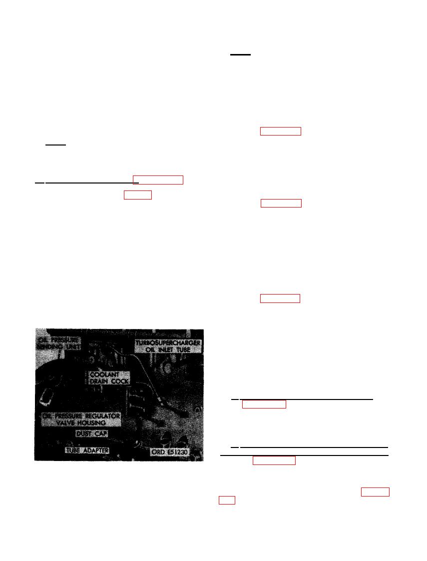 regulator housing against gasket, alining screw
Note. It may be necessary to turn 90 degree
holes. (B) Install four 3/8-inch lock washers
elbow with attached tube to permit alinement with
and 3/8 x 2 cap screws to secure oil pressure
turbosupercharger oil inlet connector during in-
regulator valve housing. (C) Install turbosuper-
stallation of turbosupercharger.
charger drain tube hose adapter in cylinder
and crankcase and tighten securely. Install dust
cap in opening to prevent entrance of dirt and
foreign material. (D) Install 3/8- inch pipe x
SUPPORT AND
ROD
1/2-inch tube, 90 degree elbow and tighten to
MOUNTING BRACKET
position shown. (E) Connect turbosupercharger
oil inlet tube to 90 degree elbow.
Refer to figure 251 and reverse the sequence
of instructions to install the oil level gage rod
Note. It may be necessary to turn 90 degree
support and generator mounting bracket.
elbow with attached tube to permit alinement of
turbosupercharger oil inlet flange during in-
stallation of turbo supercharger.
277. INSTALLATION OF FLAME HEATER
FUEL PUMP AND FUEL FILTER
b . EarlyModel Engines. Figure 490. (A)
Position a new regulator valve housing gasket
BRACKET
on cylinder and crankcase (fig. 254) and posi-
tion regulator valve housing against gasket,
Refer to figure 250 and reverse the sequence
of instructions to install the flame heater fuel
alining screw holes. (B) Secure oil pressure
regulator valve housing to cylinder and crank-
pump and fuel filter bracket.
case using four 3/8- inch lock washers and 3/8
x 2 cap screws. (C) Install turbosupercharger
278. INSTALLATION OF FLAME HEATER
oil drain hose adapter in cylinder and crank-
TUBES, WIRING HARNESS,
case. Tighten securely and install dust cap to
FUEL
prevent entry of dirt and foreign material.
OIL LEVEL GAGE, INTAKE MANIFOLD
ELBOW, FLAME HEATER IGNITION
(D) Install 1/4-inch pipe x 3/8 tube, 90 degree
elbow and tighten to approximate position shown.
UNIT, AND FLAME HEATER ASSEM-
(E) Connect turbosupercharger oil inlet tube
BLY
to 90 degree elbow. Tighten to approximate
position shown. (F) Plug open end of oil inlet
Refer to figures 245 through 249 and reverse
tube to prevent entry of dirt and foreign mater-
the sequence of illustrations and instructions
ial.
to install flame heater fuel tubes, wiring har-
ness, oil level gage, intake manifold elbow,
flame heater ignition unit, and flame heater
assembly.
PUMP ADAPTER, PRESSURE OIL
HOSE ELBOW, AND AIR COMPRESSOR
SUPPORT
a. Install Fuel Injection Pump Adapter. Re-
fer-to figure 243 and reverse the sequence of
instructions to install fuel injection pump a-
dapter. Use a new gasket between adapter and
engine f rent plate.
b. Install Fuel Injection Pump Pressure
Oil-Hose Elbow and Air Compressor Support.
Refer to figures 241 and 242 and reverse the
sequence of- illustrations and instructions to in-
stall fuel injection pump pressure oil hose
REGULATOR VALVE HOUSING, TURBO-
elbow and the air compressor support using
a new air compressor support gasket. Figure
SUPERCHARGER OIL INLET TUBE, AND
OIL DRAIN HOSE ADAPTER (EARLY
sembled engine.
MODEL ENGINES).
312
|
|
Privacy Statement - Press Release - Copyright Information. - Contact Us |
