 |
|||
|
|
|||
|
Page Title:
INSTALLATION OF FRONT AND REAR ENGINE LIFTING BRACKETS |
|
||
| ||||||||||
|
|
 272. INSTALLATION OF FRONT AND REAR
c. Install Engine Fan. Figure 488. (A) Posi-
ENGINE LIFTING BRACKETS
tion engine fan against water pump pulley and
aline screw holes. (B) Secure fan to water
a. Install Engine Rear Lifting Bracket. Refer
pump pulley using four 5/16- inch lock washers
to figure 262 and reverse the sequence of in-
and 5/16 x 3/4 cap screws.
structions to install the rear engine lifting
bracket.
OIL PRESSURE SENDING UNIT, AND
b. Install Engine Front Lifting Bracket. Re-
COOLANT DRAIN COCK
fer to figure 261 and reverse the sequence of
instructions to install f rent engine lifting brack-
a. Install Starter Adapter. Refer to figures
et.
structions to install the starter adapter. Install
a new starter adapter gasket.
SEMBLY,
THERMOSTAT HOUSING,
GENERATOR ADJUSTING STRAP, AND
b. Install Oil Pressure Sending Unit and
ENGINE FAN
Coolant Drain Cock. Refer to figures 255 and
256 and reverse the sequence of instructions
a. Install Water Pump Assembly. Refer to
to install the oil pressure sending unit and
coolant drain cock.
tion to install the water `pump assembly.
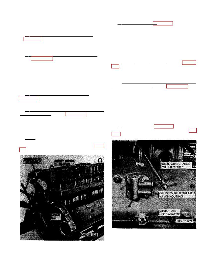
275. INSTALLATION OF OIL PRESSURE
b. Install Thermostat Housing and Generator
REGULATOR VALVE HOUSING, TURBO-
Adjusting Strap. Refer to figures 258 and 259
SUPERCHARGER OIL INLET TUBE,
and reverse the sequence of illustrations and
AND DRAIN HOSE ADAPTER
instructions to install thermostat housing and
generator adjusting strap. Use a new thermo-
a. Late Model Engines. Figure 489. (A) Posi-
stat housing gasket.
tion a new regulator valve housing gasket (fig.
Note. Do not tighten the nut securing gen-
erator adjusting strap until generator drive
belts have been installed and adjusted (par.
REGULATOR VALVE HOUSING, TURBO-
SUPERCHARGER OIL INLET TUBE, AND
OIL DRAIN TUBE ADAPTER (LATE
MODEL ENGINES).
311
|
|
Privacy Statement - Press Release - Copyright Information. - Contact Us |
