 |
|||
|
|
|||
|
Page Title:
Section II. ASSEMBLY OF ENGINE FROM SUBASSEMBLIES |
|
||
| ||||||||||
|
|
 Section II. ASSEMBLY OF ENGINE FROM SUBASSEMBLIES
Note. Upper main bearing sleeve halves are
BLY AND PISTON COOLING NOZZLES
property installed when number on bearing tab
corresponds to number on main bearing cap
a . Preparations. Support the cylinder and
and the number is on camshaft side of engine.
crankcase on suitable blocks, with the cylinder
head mounting surface resting on the blocks.
a n d reverse seauence of instructions to install
b. Camshaft Assembly. Refer to figure 310
crankshaft assembly.
and 311 and reverse the sequence of illustra-
tions to install camshaft assembly and thrust
plate.
Note. The camshaft rear bearing plug should
a . Install Main Thrust Bearing Cap. Install
not be installed until after the camshaft end play
main thrust bearing cap, with assembled lower
is established (par. 261).
sleeve bearing, in center (No. 4) position.
Install two 19/32-inch x 3/16-inch thick flat
c . Piston Cooling Nozzles. Figure 465. (A)
washers and 9/16 x 5- 1/16 cap screws to se-
Install piston cooling nozzle. (B) Secure piston
cure thrust bearing cap. Do not tighten the cap
cooling nozzle by installing 5/16-inch plain nut.
screws more than is necessary to keep bearing
(C) Install remaining five piston cooling nozzles
cap in position.
in same manner.
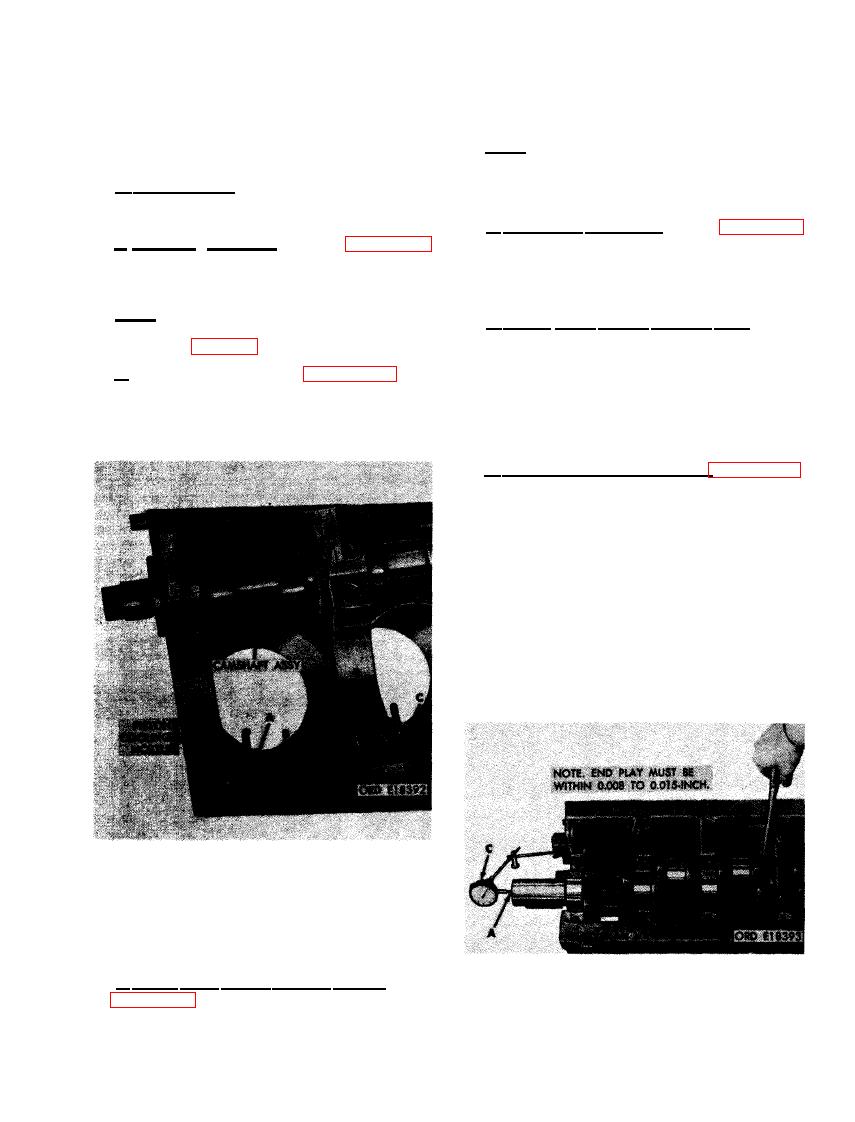
b . Check Crankshaft End Play. Figure 466.
(A) Mount dial indicator on crankcase so in-
dicator point rests on front end of crankshaft
assembly. (B) Using a heavy screwdriver be-
tween center main bearing cap and crankshaft
counterweight, push crankshaft toward rear end
of cylinder and crankcase to aline thrust bear-
ing flanges. Tighten main bearing cap screws to
a torque of 1100 pound inches. (C) Set indicator
on zero reading ("O"). (D) Using heavy duty
screwdriver, push crankshaft toward f rent end
of cylinder and crankcase to check end play.
Crankshaft end play must be within 0.008 to
0.015-inch.
NOZZLE.
BEARINGS AND CRANKSHAFT ASSEM-
BLY
a. Upper Matn Sleeve Bearing Halves. Refer
to figure 308 to install the upper main sleeve
bearing halves in cylinder and crankcase.
PLAY.
299
|
|
Privacy Statement - Press Release - Copyright Information. - Contact Us |
