 |
|||
|
|
|||
|
|
|||
| ||||||||||
|
|
 251. ASSEMBLY
e. Adjust Height of Release Levers. Adjust
height of release levers as follows.
a. Install Release Lever Needle Rollers and
Yokes. Figure 460. (A) Coat 152 needle rollers
with grease (GAA) (MIL-G-10924). Insert 19
release lever needle rollers in yoke pin bore
in release lever, using one bearing retaining
pin to hold rollers in position as they are in-
stalled. (B) Install yoke, guiding yoke pin through
needle rollers. Yoke pin must enter needle
roller pack as pin is pushed into position to
push out the temporary bearing retaining pin.
(C) Place head of yoke pin on a flat hard sur-
face and mushroom or split headless end of
yoke pin to prevent pin from working out of
position.
Note. Install the needle rollers and yokes on
the remaining three release levers in the same
manner.
b. Install Release Levers. Coat 19 release
lever needle rollers with grease (GAA) (MIL-
G 10924). Insert the 19 release lever' needle
rollers in release lever pin bore using one bear-
ing retaining pin to hold rollers in position as
they are installed, as shown in figure 454. Refer
to figure 453 and reverse the sequence of in-
structions to install the four release lever and
yoke assemblies on the pressure plate.
Note. Spread or split headless end of release
lever pins to prevent them from working out
of position.
LEVER SPACER BLOCKS BEFORE RE-
LEASE LEVER HEIGHT ADJUSTMENT.
c. Install Pressure Springs. If pressure plate
has been resurfaced, install 1/32- inch thick
spacers (fig. 447) under pressure springs for
each 1/32- inch removed from the pressure plate
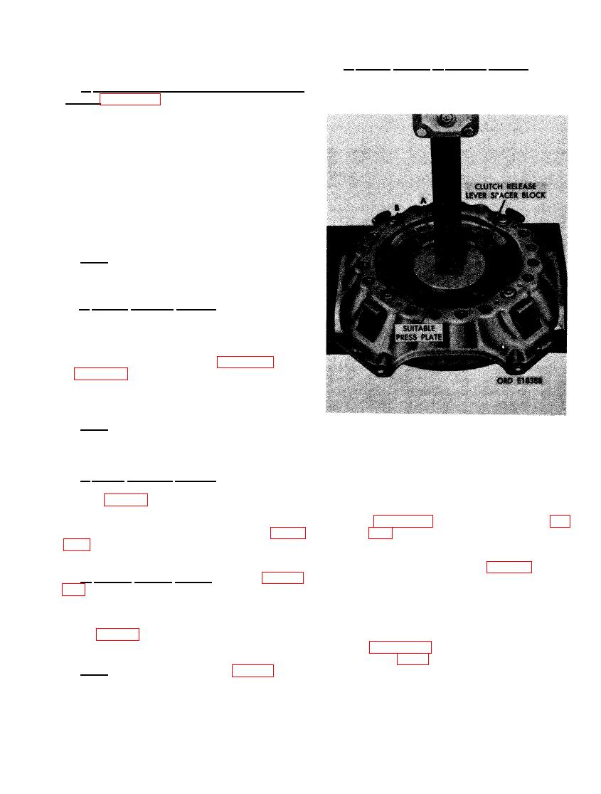
(1) Figure 461. (A) Remove cross bar (fig.
surface. The spacers will be necessary in main-
taining original spring tension. Refer to figure
on throw-out bearing contact surface of
to install pressure springs.
release levers. The use of press plate,
instead of cross bar (fig. 451), will
allow more release lever travel for
d. Install Clutch Cover. Refer to figures
clutch release lever spacer block in-
stallation. (B) Install one clutch release
trations and instructions to assemble the clutch
lever spacer block between release
cover and pressure plate assembly. Aline
scribe marks on clutch cover and pressure
lever and clutch cover as shown.
plate (fig. 449) before installing release lever
adjusting nuts.
(2) Figure 462. (A) Position clutch spacer
plate (fig. 34) against clutch cover pres-
Note. Do not install lock plates (fig. 450) and
sure plate clutch facing surface as you
would when positioning driven member
Cap screws until release lever height has been
adjusted.
during clutch installation. (B) Secure
|
|
Privacy Statement - Press Release - Copyright Information. - Contact Us |
