 |
|||
|
|
|||
|
Page Title:
Section XII. REBUILD OF OIL FILTERS, OIL COOLER AND OIL FILTER HOUSING, AND OIL COOLER |
|
||
| ||||||||||
|
|
 Section XII. REBUILD OF OIL FILTERS, OIL COOLER AND
OIL FILTER HOUSING, AND OIL COOLER
210. OIL FILTERS
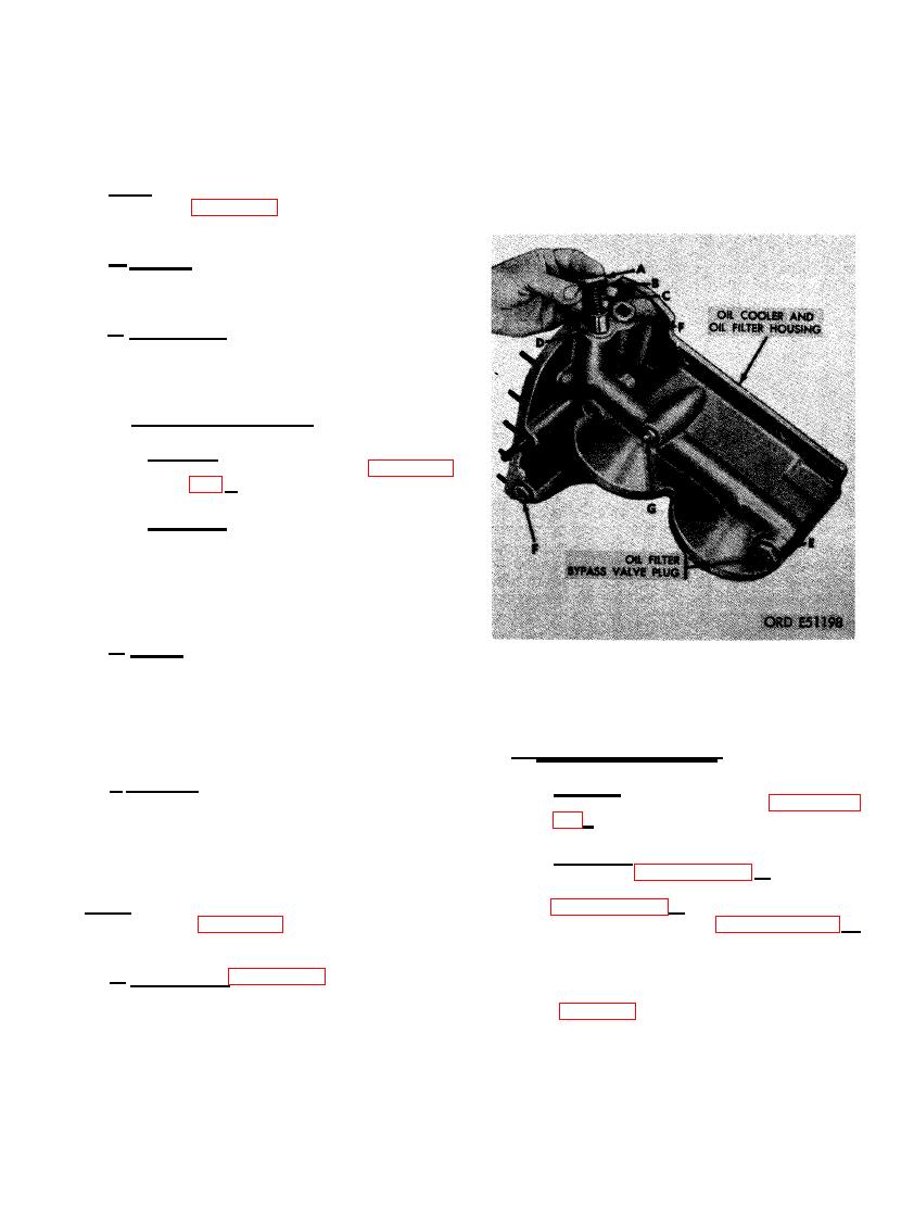
related parts in the same manner as described
in steps A through D, above. (F) Remove two
Note. The key letters shown below in paren-
3/4- inch pipe plugs. (G) Remove 3/8- inch pipe
these refer to figure 402 except where other-
plug.
wise indicated.
a . General. Both oil filters are identical.
For instructional purposes only one oil filter
will be overhauled.
b. Disassembly. Remove the sealing cup
(A-5) and retaining spring (A-4) from the bar
(A-1). Pull bar out of filter case (A-3) and
discard washer (A-2).
--. Cleaning and Inspection.
c
(1) Cleaning. Clean the filter case (A-3)
and related parts as directed in para-
graph 152 c.
(2) Inspection. Inspect the filter case (A-3)
for dents and damaged gasket surfaces.
Inspect bar (A-1) for cracks, damaged
threads, and damaged gasket surfaces.
Examine the retaining spring (A-4) for
cracked and set condition.
d. Repair. Repair minor damage to filter case
(A-3) and bar (A-1). Gasket surfaces may be
resurfaced using crocus cloth placed on a flat
BYPASS VALVE PLUNGERS AND PIPE
s u r f a c e . Replace filter case and bar when
PLUGS.
cracked, distorted, or when gasket surfaces
cannot be repaired. Replace the retaining spring
(A-4) when cracked or in a set condition.
b. Cleaning and Inspection.
e. Assembly Position new washer (A-2) on
(1) Cleaning. Clean the housing (B-2) and
related parts as directed in paragraph
bar (A-1) and insert bar into filter case (A-3).
'
Position retaining spring (A- 4) and install seal-
152 c.
ing cup (A-5) on bar.
(2) Inspection. Inspect the housing (B- 2) as
directed in paragraph 153 b. Inspect the
helical coil inserts (B- 1) as directed in
Note. The key letters shown below in paren-
theses refer to figure 402 except where other-
B-5) as directed in paragraph 153 d .
wise indicated.
Check the bypass valve plungers (M and
W), housing (B- 2), and valve plunger
a. Disassembly. Figure 403. (A) Remove oil
springs (Q and U) against limits spec-
ified in repair and rebuild standards
cooler bypass valve plug from oil cooler and
oil filter housing. (B) Remove and discard oil
plungers and plunger bores in the hous-
cooler bypass valve plain washer (gasket). (C)
ing for scratches and wear patterns.
Remove oil cooler bypass valve plunger spring.
Inspect valve plunger s p r i n g s for
(D) Remove oil cooler bypass valve plunger.
cracked and set condition.
(E) Remove the oil filter bypass valve plug and
251
|
|
Privacy Statement - Press Release - Copyright Information. - Contact Us |
