 |
|||
|
|
|||
|
Page Title:
Section IX. REBUILD OF VALVE ROCKER ARMS, SHAFTS, PUSH RODS, TAPPETS, AND RELATED CYLINDER HEAD PARTS. |
|
||
| ||||||||||
|
|
 are damaged. Grind slightly pitted or
burned valves that do not seat perfectly
to limits specified in figure 387. Re-
place valves that cannot be ground to
these limits. Check valve length from
seat contact to tip of stem after grinding
as shown in figure 387. Replace valve
if length is not within limits specified
in repair and
r e b u i l d standards
(2) Valve springs. Replace inner spring
(K-3) and outer spring (K-4) when
worn, cracked, or other-wise damaged.
Replace springs that do not meet limits
specifed in repair and rebuild stan-
dards (par. 294).
(3) Valve spring retainers. Replace worn
or cracked valve spring retainer (K-2).
(4) Valve rotators. Replace valve rotators
(K-5) when inner section does not rotate
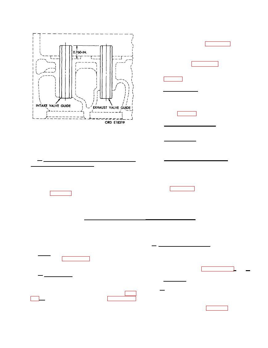
SETTING HEIGHT OF VALVE GUIDES IN
freely, or when it is worn or cracked.
CYLINDER HEAD.
(5) Valve spring retainer locks. Replace
b. Valves, Springs, Retainers, Rotators, and
v a l v e spring retainer lock (K-1) if
Valve Spring Retainer Locks.
worn or cracked.
(1) Valves. Replace warped intake valves
201. ASSEMBLY
(K-14) or exhaust valves (K-13) or
valves which do not meet limits spec-
ified in repair and rebuild standards
Refer to figures 380 through 384 and re-
verse the sequence of illustrations and instruc-
pitted or burned faces. Replace valves
tions to assemble the front cylinder head. As-
having badly pitted, scored, or scratched
semble the rear cylinder head in the same
stems. Replace valves if locking grooves
manner.
Section IX. REBUILD OF VALVE ROCKER ARMS, SHAFTS, PUSH RODS,
TAPPETS, AND RELATED CYLINDER HEAD PARTS.
b. Cleaning and Inspection.
Note. The key letters shown below in paren-
(1) Cleaning. Clean six valve rocker arms
these refer to figure 385 except where other-
(C), rocker arm shaft (E), three rocker
wise indicated.
arm supports (F) and two thrust springs
(J) as directed in paragraphs 152 c and d.
a . Disassembly. The front and rear sets of
valve rocker arms are identical and interchanEe-
(.2) .Inspection.
.
able. For instructional purposes, the front set
of valve rocker arms will be disassembled.
(a) Inspect valve rocker arm assemblies
(C) for cracks using a magnifying
Disassemble the front set of rocker arms (par.
glass and strong light. Check bearing
through 186. Disassemble the rear set of rocker
against limits specified in repair and
arms in the same manner.
rebuild standards (par. 294). Inspect
|
|
Privacy Statement - Press Release - Copyright Information. - Contact Us |
