 |
|||
|
|
|||
|
Page Title:
Section VIII. REBUILD OF CYLINDER HEAD ASSEMBLY |
|
||
| ||||||||||
|
|
 (2) Inspection. Inspect pressure oil pump
b. Cleaning and Inspection.
outlet tube (X) for dents, cracks, loose
flange, a n d flattened areas. Check
(1) Cleaning. Clean tachometer adapter (G),
mounting flange and adapter with a
and tachometer take-off adapter (F) as
straight edge for warpage.
directed in paragraph 152 b.
c. Repair Correct minor warpage of the
(2) Inspection. Inspect tachometer adapter
mounting flange of the pressure oil pump outlet
(G) for damaged threads and cracks.
tube (X) or the outlet tube adapter by working
Inspect adapter shaft (G1) for burs and
the part across a sheet of crocus cloth held
wear. Insert shaft in tachometer a-
tightly on a flat surface. Replace an outlet tube
dapter and rotate shaft. Shaft must ro-
or adapter if damaged, broken, or unservice-
tate freely. Inspect tachometer take-off
able.
adapter (F) for damaged threads and
cracks.
d. Assembly. The assembly and installation
of the pressure oil pump outlet tube (X) and
c. Repair. Repair damaged threads on tacho-
adapter (S) is performed during assembly of
meter adapter (G) with a die. Remove minor
the engine (par. 266).
burs and scratches from adapter shaft (G-1)
with crocus cloth dipped in dry-cleaning solvent
or mineral spirits paint thinner. Replace bent
or scratched shaft. Replace tachometer adapters
which do not rotate freely. Repair damaged
Note. The key letters shown below in paren-
threads on tachometer take-off adpater (F) with
theses refer to figure 352.
a die. Replace cracked take-off adapters.
a. Removal. The removal of the tachometer
d. Installation. Installation of the tachometer
a d a p t e r associated parts was performed
adapter is performed during assembly of the
during disassembly of the engine (par. 140).
engine (par. 264).
Section VIII. REBUILD OF CYLINDER HEAD ASSEMBLY
198. DISASSEMBLY
a. General. The f rent and rear cylinder head
a s s e m b l i e s identical and are interchange-
able. For instructional purposes the f rent cyl-
inder head will be overhauled.
b. Disassembly. Disassemble the front cyl-
inder head as follows.
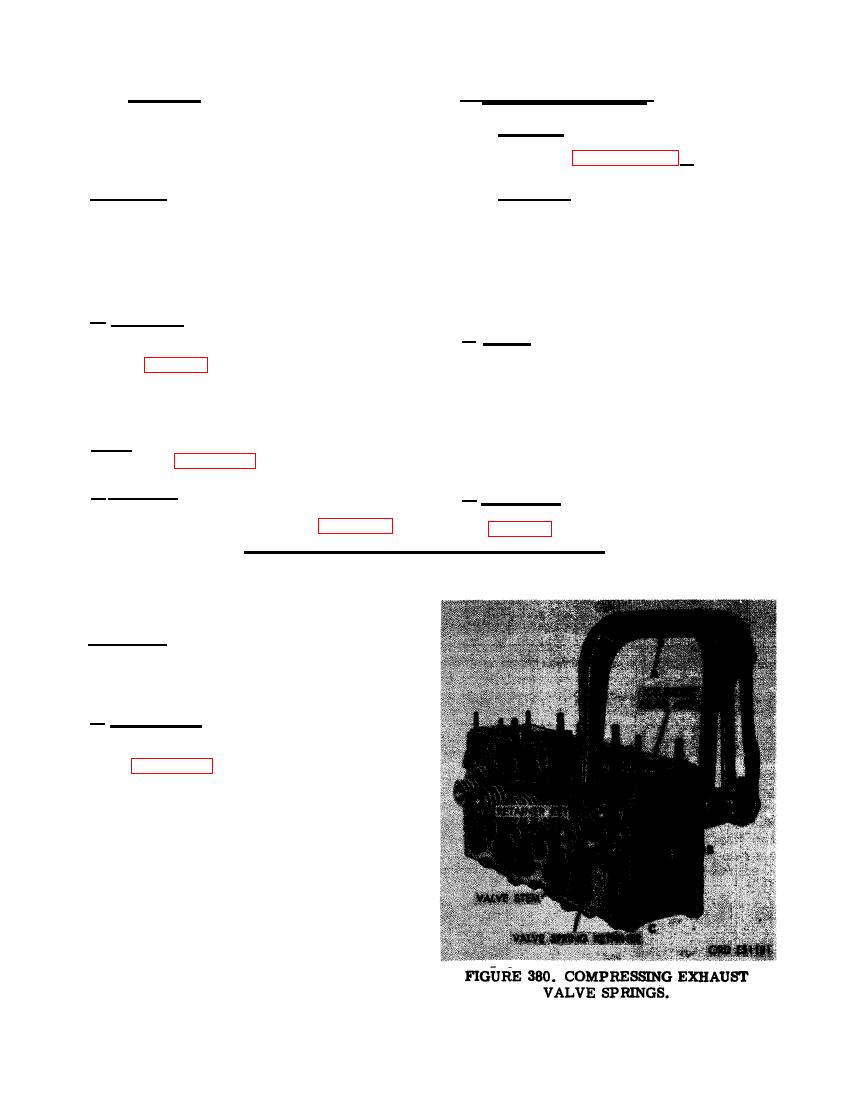
(1) Figure 380. (A) Compress exhaust valve
springs using a suitable valve spring
compressor. (B) Remove two exhaust
valve spring retainer keys from valve
stem. Carefully release valve spring
c o m p r e s s o r to relieve valve spring
tension. (C) Remove valve spring re-
tainer.
236
|
|
Privacy Statement - Press Release - Copyright Information. - Contact Us |
