 |
|||
|
|
|||
|
Page Title:
FIGURE 331. CYLINDER LINER REMOVER AND REPLACER KIT - 8722925 SHOWING POSITION OF SHOE AGAINST LINER DURING LINER REMOVAL - S... |
|
||
| ||||||||||
|
|
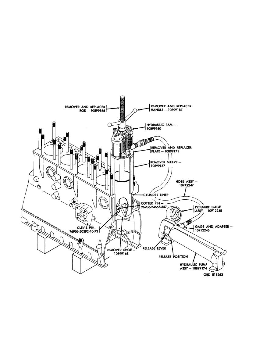 (4) Position the hydraulic ram - 10899160
(2) Position the rod up through the cyl-
and remover and replacer handle -
inder liner, from bottom of crankcase,
10899187 on rod. Tighten handle clock-
until the shoe seats in the bottom of
wise until shoe, sleeve, plate, and ram
the liner. With an assistant holding the
are properly seated.
rod and shoe in position, position re-
mover sleeve - 10899167 over liner to
(5) Remove protective caps from hydraulic
be removed.
ram inlet. Install hose and gage adapter
- 10912246 in the hydraulic pump as-
(3) Install remover and replacer plate -
sembly - 10899174 and connect hose as-
10899171 on sleeve with large diameter
sembly to the ram inlet.
away from sleeve.
POSITION OF SHOE AGAINST LINER DURING LINER REMOVAL - SECTIONAL VIEW.
203
|
|
Privacy Statement - Press Release - Copyright Information. - Contact Us |
