 |
|||
|
|
|||
|
|
|||
| ||||||||||
|
|
 yoke assembly, flat washer. and plain nut as
outlined in c, above. Tighten plain nut until all
parts are seated and alined. Apply a light
coating of engine oil OE-10 (MIL-0-2104) on
outside diameter of bearing. Oil hole in bearing
must be alined with grease pencil mark made
in b, above. Slowly tighten plain nut until bear-
ing is pulled into bore and flush with front
edge. Use a suitable pin through hole in the
threaded end of the shaft to keep it from turning
f . Installation of remaining bearings will
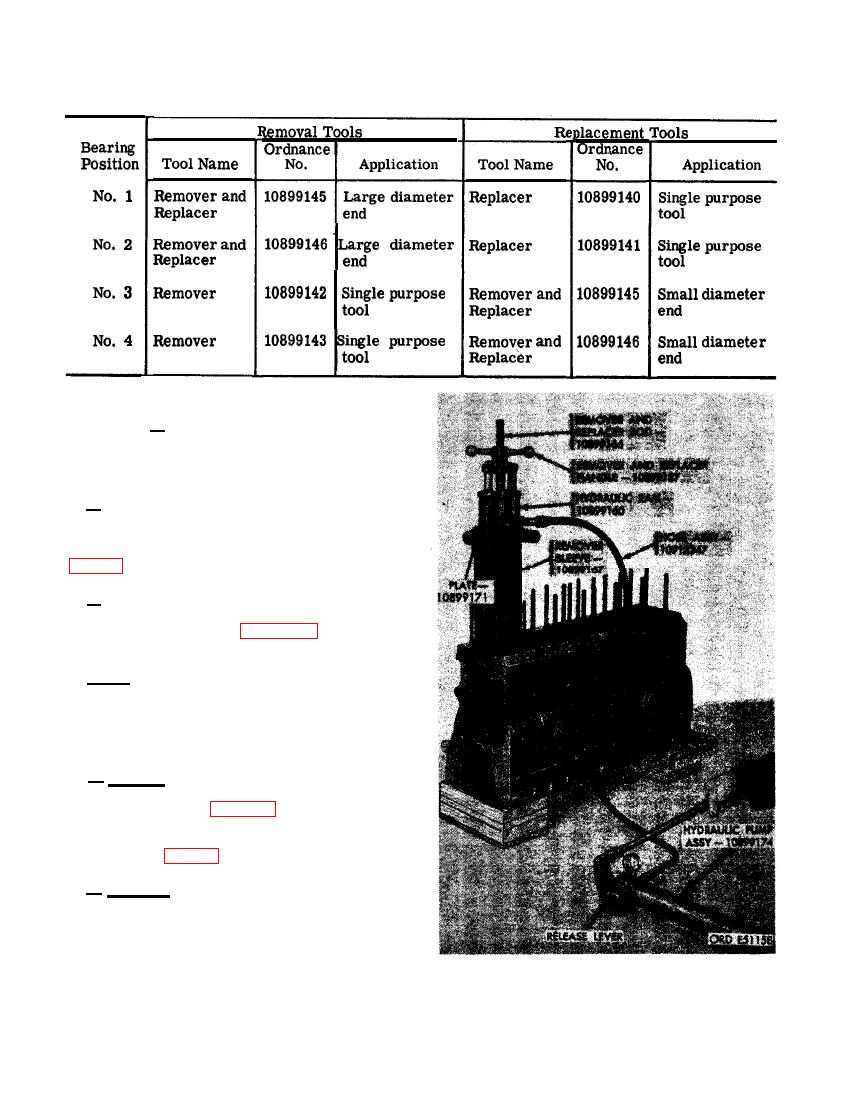
be similar to the above. Select proper remover
and/or replacer from Table IV and install
bearings.
Note. Replacement camshaft bushing-type
bearings are finished to size and do not need
machining after installation.
a . General. Replace cylinder liners which
do not meet requirements specified in repair
and rebuild standards (par. 292). When neces-
sary to replace cylinder liners use remover
and replacer kit - 8722925 and hydraulic ram
kit - 10912249 (figs. 24, 330, and 331).
b. Removal.
(1) Assemble remover and replacer rod -
10899166 and remover shoe - 10899168
and secure with clevis pin - 96906-
20392-10-73 and cotter pin - 96906-
24665-375.
LINER.
202
|
|
Privacy Statement - Press Release - Copyright Information. - Contact Us |
