 |
|||
|
|
|||
|
Page Title:
REPAIR OF CYLINDER AND CRANKCASE AND MISCELLANEOUS ITEMS |
|
||
| ||||||||||
|
|
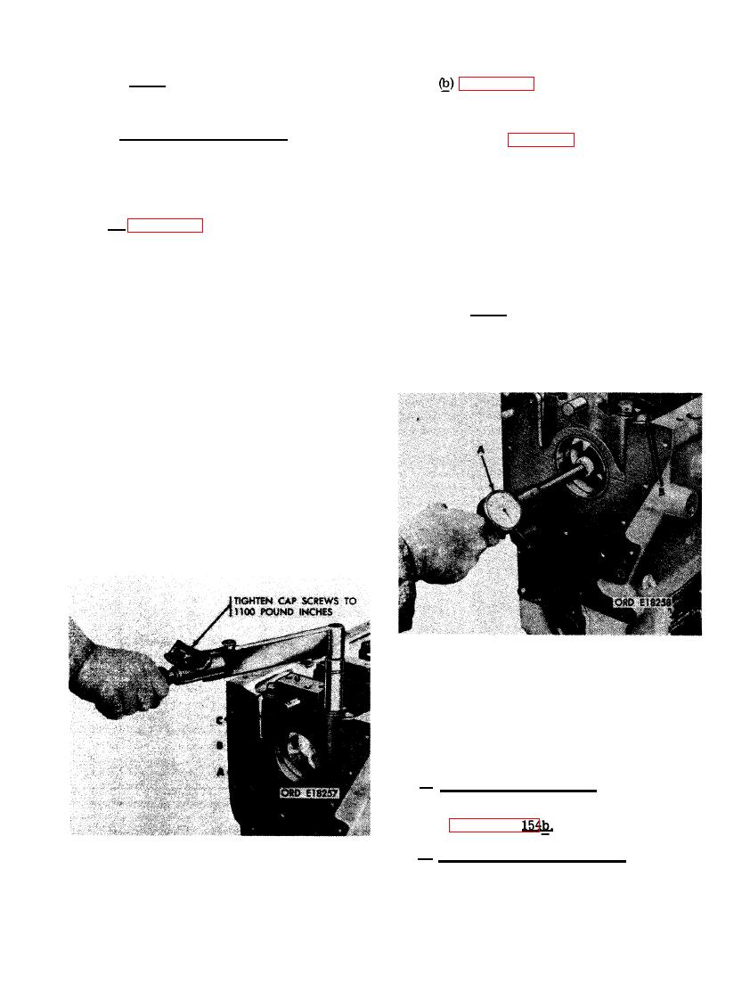 Note. Check lower main thrust sleeve
bearing half in bore of thrust bearing
of the main bearings with a dial in-
cap in the same manner.
dicator as shown, and against limits
specified in repair and rebuild stan-
(12) Check main bearing bores. Apply a thin
dards (par. 292). Replace bearing
coat of Prussian blue to backs of upper
halves not meeting the repair and re-
and lower bearing halves. The blue
build requirements. Remove the main
transfer will show bearing contact area
bearing caps and bearing halves from
in crankcase bore. Check main bearing
the crankcase and check the contact
bores as follows.
surface as indicated by Prussian blue
(a) Figure 326. (A) Install the remaining
transfer. Replace bearing halves that
do not make 75 percent contact with
six upper main sleeve bearing halves
in their original location in bearing
crankcase bearing bores and recheck
new bearings. (B) Check the remaining
bore of cylinder and crankcase. Install
bearing bores in the same manner.
the remaining six lower main sleeve
bearing halves in their respective
Note. After main bearing bores have
bearing caps. (B) Apply a light coating
of engine oil OE-10 (MIL-0-2104) to
been checked, remove all main bearing
the edges of the seven main bearing
caps and bearing halves from cylinder
caps with sleeve bearing halves in-
and crankcase.
stalled. Install bearing caps with bear-
ing halves in their proper location in
the crankcase, according to the loca-
tion numbers stamped on the cap. The
location numbers appear on the cam-
shaft side of the cap. (C) Apply a small
amount of mica-base antiseize com-
pound (MIL-A-13881) to the threaded
area of each main bearing cap screw.
Install two plain washers and cap
screws through each main bearing cap.
Tighten each pair of cap screws al-
ternately to a final torque of 1100
pound inches as shown.
WITH SLEEVE BEARINGS HALVES IN-
STALLED USING A DIAL INDICATOR.
AND MISCELLANEOUS ITEMS
a. Cylinder and Crankcase. Repair cylinder
and crankcase and main bearing caps having
nicks, burs, and raised metal surfaces as out-
lined in paragraph
b . Main Sleeve Bearing Halves. Repairs to
the main sleeve bearing halves are limited to
BEARING CAP SCREWS PRIOR TO MAIN
replacement of unserviceable bearings.
BEARING BORE CHECK.
199
|
|
Privacy Statement - Press Release - Copyright Information. - Contact Us |
