 |
|||
|
|
|||
|
Page Title:
REMOVAL OF TIMING GEAR COVER ASSEMBLY |
|
||
| ||||||||||
|
|
 141. REMOVAL OF TIMING GEAR COVER AS-
SEMBLY
a. General. The timing gear cover assembly
houses the crankshaft gear, camshaft gear, and
oil pump idler gear.
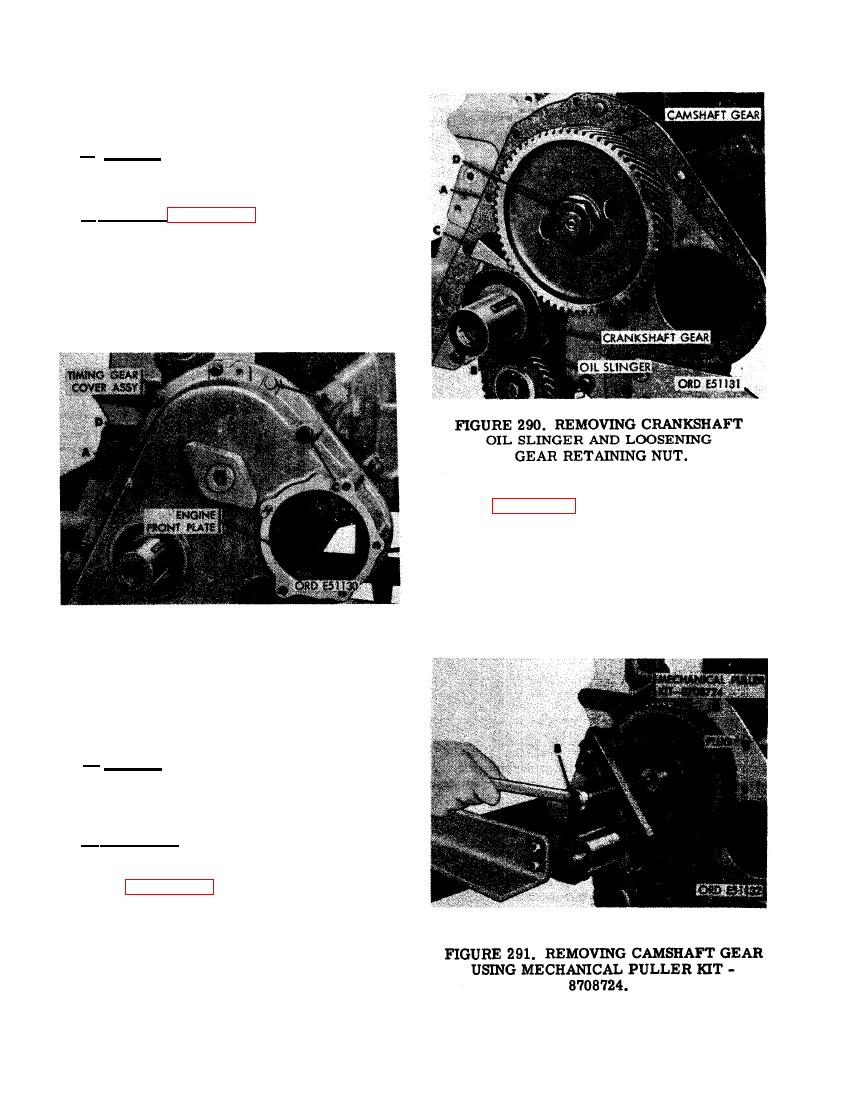
b. Removal. Figure 289. (A) Remove seven
3/8 x 1-1/4 cap screws and 3/8-inch lock
washers. (B) Remove 3/8-inch plain nut, 3/8-
inch lock washer, and 3/8 x 1-1/4 cap screw.
(C) Remove 1/2-inch plain nut, 1/2-inch lock
washer, and 1/2 x 2-3/4 cap screw. (D) Remove
timing gear cover assembly.
(2) Figure 291. (A) Install 3/8-16 puller
screws of mechanical puller kit -
8708724 into puller screw holes in cam-
shaft gear. Insert suitable plug against
end of camshaft assembly and run puller
jack screw against plug. (B) Pull cam-
shaft gear from end of camshaft assem-
bly.
TIMING GEAR COVER ASSEMBLY.
CRANKSHAFT GEAR
a . General. The camshaft gear is driven
by the crankshaft gear. The two gears have
timing marks on the teeth to aid in timing the
engine.
b . R e m o v a l . Remove camshaft gear and
crankshaft gear as follows.
(1) Figure 290. (A) Remove and discard
cover gasket. (B) Remove crankshaft
oil slinger. (C) Wedge a wooden block
between camshaft and crankshaft gears
to prevent gears from turning while
camshaft gear retaining nut is loosened.
(D) Loosen camshaft gear retaining nut.
176
|
|
Privacy Statement - Press Release - Copyright Information. - Contact Us |