 |
|||
|
|
|||
|
Page Title:
FIGURE 267. REMOVING OR INSTALLING INTAKE AND EXHAUST MANIFOLDS AS A UNIT |
|
||
| ||||||||||
|
|
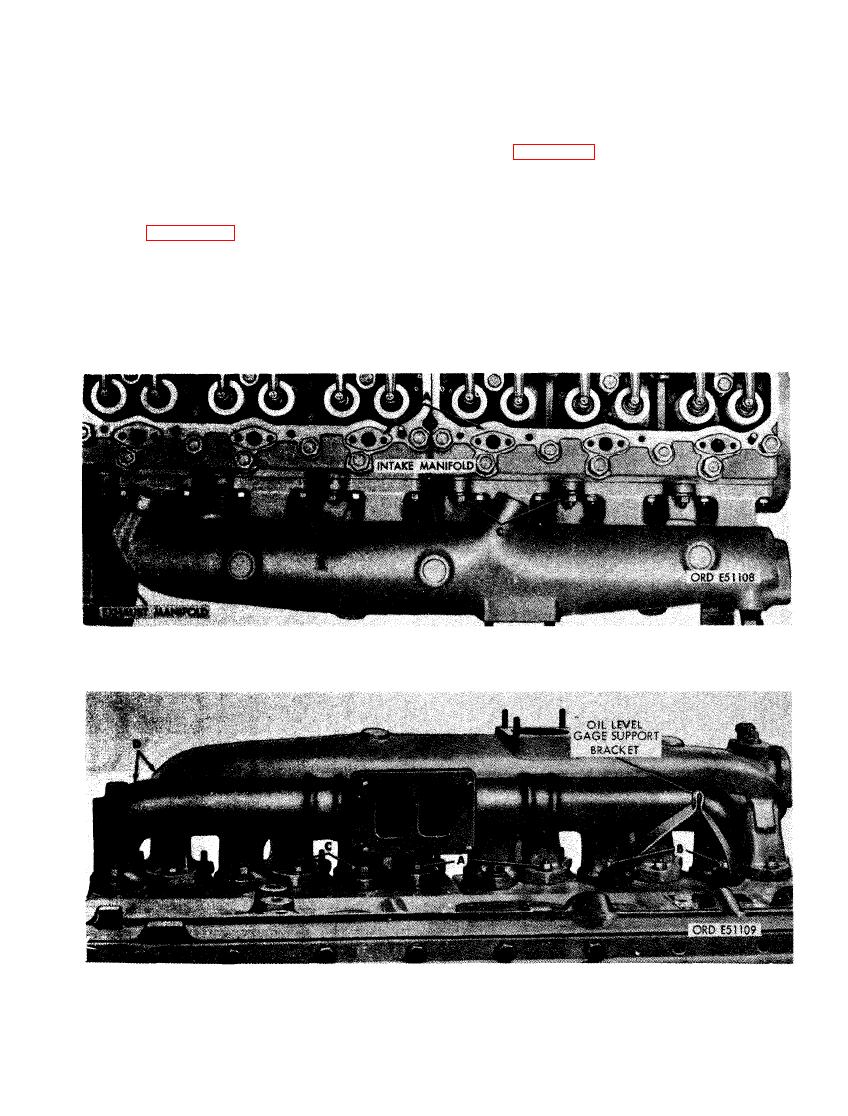 and 7/16-inch flat washers securing
cylinder head assembly. (C) Remove
top flanges of exhaust manifold to cyl-
front cylinder head water outlet mani-
inder head assemblies.
fold. (D) Remove six 5/16 x 2-1/4 cap
screws and 5/16-inch lock washers se-
(3) Figure 267. (A) Remove six 5/16-inch
curing rear cylinder head water outlet
plain nuts and 5/16-inch flat washers
manifold to rear cylinder head assem-
securing bottom flanges of intake mani-
bly. (E) Remove rear cylinder head
fold to cylinder head assemblies. (B)
water outlet manifold.
Remove two 7/16-inch self-locking nuts
and remove oil level gage rod support
(2) Figure 266. (A) Remove and discard
clamp brackets. (C) Remove four 7/16-
six cylinder head water outlet manifold
inch self-locking nuts and 7/16-inch
gaskets. (B) Remove twelve 5/16-inch
flat washers securing bottom flanges of
plain nuts and 5/16-inch flat washers
exhaust manifold to cylinder head as-
securing top flanges of intake manifold
semblies. (D) Remove intake and ex-
to cylinder head assemblies. (C) Re-
haust manifolds.
move six 7/16-inch self-locking nuts
MANIFOLDS AT CYLINDER HEAD ASSEMBLIES - TOP VIEW.
167
|
|
Privacy Statement - Press Release - Copyright Information. - Contact Us |
