 |
|||
|
|
|||
|
Page Title:
FIGURE 257. REMOVING ENGINE FAN. |
|
||
| ||||||||||
|
|
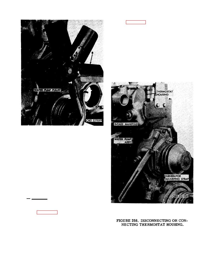 (2) Figure 258. (A) Remove 3/8-inch plain
nut and 3/8-inch lock washer securing
generator adjusting strap to water pump
assembly. (B) Remove generator adjust-
ing strap. (C) Loosen two 2-inch od hose
clamps securing thermostat housing-
to-water pump hose. (D) Remove two
3/8 x 3-5/8 cap screws and 3/8-inch
flat washers securing thermostat hous-
ing to intake manifold.
b. Removal. Remove engine fan, thermostat
housing, and water pump assembly as follows.
(1) Figure 257. (A) Remove four 5/16 x
3/4 cap screws and 5/16-inch lock
washers securing engine fan to water
pump pulley. (B) Remove engine fan.
163
|
|
Privacy Statement - Press Release - Copyright Information. - Contact Us |
