 |
|||
|
|
|||
|
Page Title:
REMOVAL OF FUEL FILTER ASSEMBLY |
|
||
| ||||||||||
|
|
 b. Generator Assembly. Remove generator
ass-embly and drive belts following instructions
for figure 41. Remove generator pulley follow-
ing instructions for figure 42.
c. Turbosupercharger Assembly. Remove
turbosupercharger assembly following instruc-
tions for figures 44 through 47 and 49 through 53.
d. Fuel Injection Pump Assembly. Remove
fuel injection pump assembly following instruc-
tions for figures 56 through 61 and 66 through 76.
e. Flame Heater Fuel Pump Assembly. Re-
move flame heater fuel pump assembly following
instructions for figures 78 through 80.
f. Air Compressor Assembly. Remove air
compressor assembly and drive belt following
instructions for figures 80 through 85.
116. GENERAL
the accessories removed and ready for disas-
sembly. For instructional purposes the disas-
sembly procedures will begin on the left side
AT FUEL FILTER ASSEMBLY.
of engine and continue until all components
are removed from that side. The remainder of
the disassembly procedure will continue to the
right side until partially disassembled. To com-
plete the disassembly procedures, remove the
engine from the overhaul stand. Figures 226
through 312 present a step-by-step procedure
for disassembly of the engine.
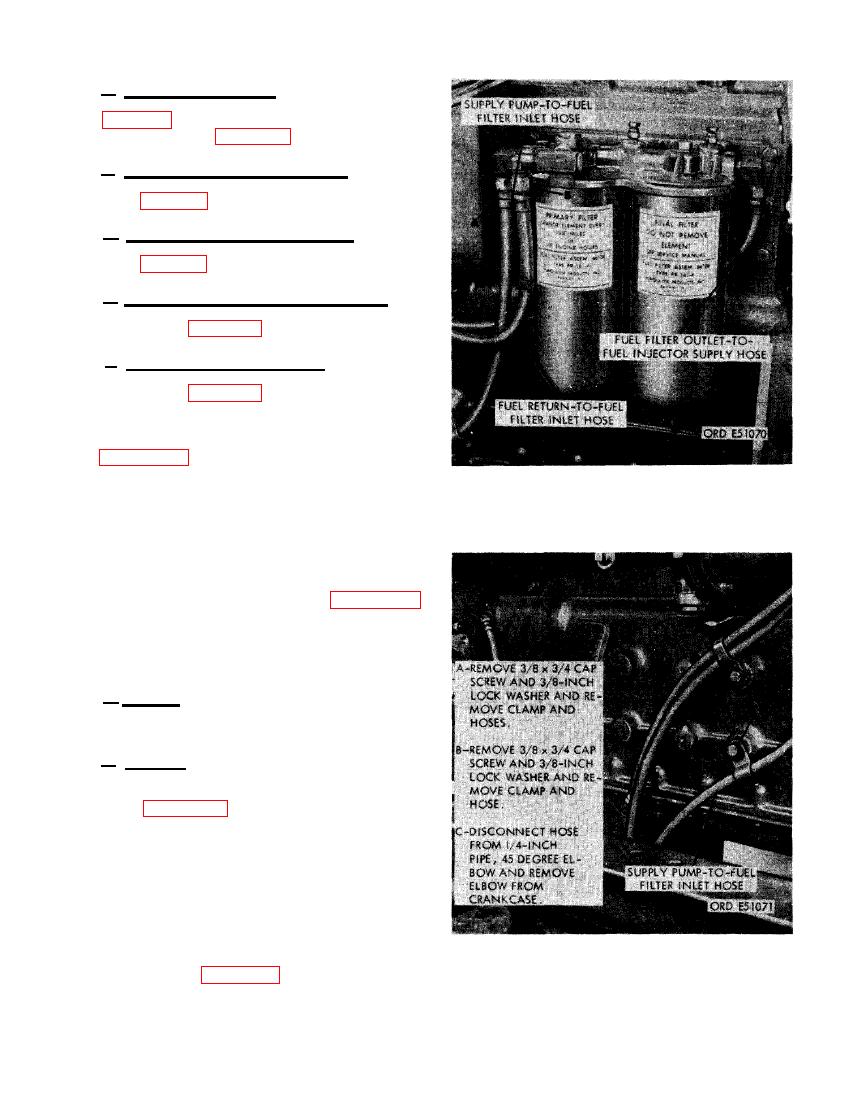
a. General. The fuel filter assembly, con-
sisting of two filters, primary and secondary,
is mounted on the upper left rear of the engine.
b. Removal. Remove the fuel filter assembly
as follows.
(1) Figure 226. (A) Disconnect and remove
supply pump-to- fuel filter inlet hose
from 3/8 x 1/4 pipe reducer in filter
head. (B) Disconnect and remove fuel
injection overflow and fuel return-to-
fuel filter inlet hose from 3/8- inch pipe
tee. (C) Disconnect and remove fuel
filter outlet-to-fuel injector supply hose
from 3/8- inch, 90 degree street elbow.
(2) Refer to figure 227 and remove fuel and
FUEL AND OIL HOSES FROM ENGINE.
oil hoses from the engine.
151
|
|
Privacy Statement - Press Release - Copyright Information. - Contact Us |
