 |
|||
|
|
|||
|
Page Title:
CHECKING NOZZLE OPENING BREAK PRESSURE AND SPRAY PATTERN |
|
||
| ||||||||||
|
|
 b. Install Injector Nozzle and Holder Assem-
bly-in Tester. Install nozzle and holder assembly
on the fuel injector nozzle tester (par. 83c) and
perform tests outlined in paragraph 83d. -
--
c. Repair and Replacement. Repair or re-
place defective nozzles as directed in paragraph
VALVES
a. General. When checking and/or adjusting
valve clearance, it is necessary to remove the
crankcase breather adapter and the cylinder head
covers.
b. Removal of Components before Valve Ad-
justment. Remove the crankcase breather adap-
ter and the front cylinder head cover following
instructions in figure 62. The rear cover is re-
moved in the same manner as the front cover.
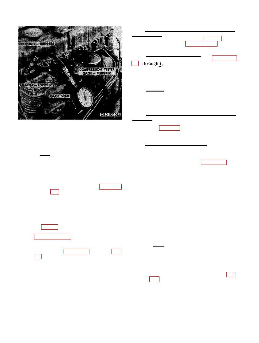
PRESSION USING COMPRESSION TESTER
GAGE -10899180, COUPLING -10899184,
c. Valve Clearance Adjustment.
AND ADAPTER - 10899183.
Note. Before checking or adjusting valve
Note. Compression pressure readings
clearance both valves must be closed on the
between cylinders Should not vary more
cylinder being checked. Refer to figure 183 and
than 25 psi ana pressure should not
follow the sequence of instructions to adjust in-
fall below 475 psi. Low compression
take and exhaust valve clearance. Valve clear-
on one or more cylinders causes
ance must be checked and set when the tappet
starting difficulty and poor engine per-
is on the base circle of the camshaft.
formance. When compression is low on
one or more cylinders, refer to para-
graph 49 for troubleshooting engine
(1) Rotate the crankshaft clockwise as
assembly and for corrective action.
viewed at the fan end, until cylinder No.
1 intake valve rocker arm is in its open
(4) During the cylinder compression test
position (valve open). At this position
operation, check all fuel injector nozzle
cylinder No. 1 exhaust valve is closed
and holder assemblies for satisfactory
and tappet is on base circle of cam-
operation. Remove fuel return tee (step
shaft. Clearance adjustment should be
A, fig. 150) and test fuel injector nozzle
made at this point.
and holder assemblies as. directed in
paragraph 83c and d l
Note. In each cylinder the valve to the
(5) Install fuel return tee in nozzle assem-
fan end is the intake valve, and the
bly. Refer to figures 148 and 149 (par.
valve to the flywheel end is the exhaust
valve.
tions and instructions to install the fuel
(2) Insert the correct size feeler gage be-
injector nozzle and holder assemblies.
tween the valve stem and the rocker
arm pad and check the' clearance (fig.
PRESSURE AND SPRAY PATTERN
ance is 0.015-inch (cold) and the cor-
rect exhaust valve clearance is 0.025 -
a. General. For instructional purposes in this
inch (cold). Loosen adjusting screw nut
section assumed that troubleshooting in-
and turn adjusting screw to obtain pro-
dicated defective nozzles and the nozzle and
per clearance. After adjustment is
holders have been removed from the engine.
made, tighten adjusting screw lock nut.
144
|
|
Privacy Statement - Press Release - Copyright Information. - Contact Us |
