 |
|||
|
|
|||
|
Page Title:
FIGURE 217. REMOVING CAMSHAFT GEAR USING MECHANICAL PULLER KIT - 8708724. |
|
||
| ||||||||||
|
|
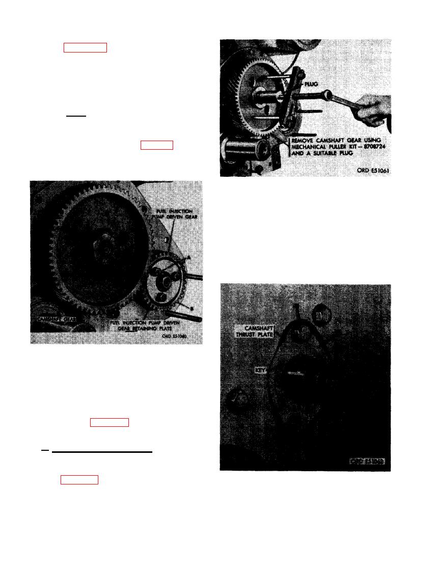 (12) Figure 216. (A) Remove three 3/8 x
1-1/4 cap screws and 3/8- inch lock
washers securing injection pump driven
gear and retaining plate. (B) Remove
injection pump driven gear retaining
plate and gear. (C) Remove camshaft
gear retaining nut.
Note. Removing injection pump driven
gear will disturb fuel injection pump
timing in relation to engine valve timing.
The fuel injection pump must be retimed
when gear is installed (par. 106).
USING MECHANICAL PULLER KIT -
8708724.
in keyway. (B) Check thrust surface of
camshaft thrust plate. Thrust plate
must have an even wear pattern and
no signs of damage which may cause
excessive camshaft end play. (C) Thrust
plate retaining screws must be tight.
DRIVEN GEAR AND/OR REMOVING OR
INSTALLING CAMSHAFT GEAR
RETAINING NUT.
(13) Refer to figure 217 and remove cam-
shaft gear.
b. Inspection and Installation. Inspect and
install crankshaft gear, injection pump driven
gear, and camshaft gear as follows.
(1) Figure 218. (A) Check condition of cam-
shaft gear key. Key must be in proper
CAMSHAFT GEAR KEY AND THRUST
position, not worn, and must fit tight
PLATE WEAR.
140
|
|
Privacy Statement - Press Release - Copyright Information. - Contact Us |
