 |
|||
|
|
|||
|
|
|||
| ||||||||||
|
|
 (2) Refer to figures 202 and 203 and re-
verse the sequence of illustrations and
instructions to install the retaining bolt
and the lock plate.
Note. When bolt holes in lock plate do
not aline with threaded holes in pulley,
the plate can be turned over and posi-
tioned so the holes are alined.
(3) Refer to figures 80 through 82 and re-
verse the sequence of illustrations and
instructions to install air compressor
drive belt.
(4) Adjust air compressor drive belt de-
flection following instructions for fig-
ure 87.
(5) Refer to figure 41 and reverse the se-
quence of instructions to install the en-
gine fan and generator drive belts.
(6) Adjust engine fan and generator drive
belt deflection following instructions for
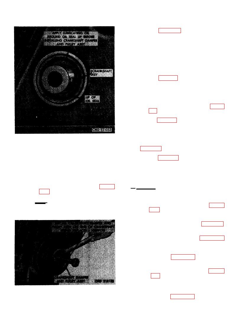
BEFORE INSTALLING CRANKSHAFT
DAMPER AND PULLEY ASSEMBLY.
(7) Refer to figure 112 and follow the se-
quence of instructions to install the en-
(1) Aline keyway in crankshaft pulley hub
gine fan.
with key in crankshaft and start crank-
shaft damper and pulley assembly on
end of crankshaft. Install crankshaft
damper and pulley assembly on crank-
a. Removal. Remove crankshaft front oil
shaft following instructions for fig-
seal as follows.
ure 208.
(1) Remove engine fan from water pump
Note. Hold replacer bolt stationary
pulley following instructions in fig-
while turning plain nut to seat damper
ure 112.
and pulley assembly.
(2) Remove engine fan and generator drive
belts following instructions in figure 41.
(3) Remove air compressor drive belt fol-
lowing the instructions in figures 80
through 82.
(4) Remove water pump assembly following
instructions in figures 114 through 116.
(5) Remove crankshaft damper and pulley
assembly following instructions in fig-
ures 201 through 203.
(6) Remove oil pan and flame heater fuel
pump and fuel filter bracket following
DAMPER AND PULLEY ASSEMBLY.
instructions in figures 198 through 200.
136
|
|
Privacy Statement - Press Release - Copyright Information. - Contact Us |
